Printer 710-810 v9 ProFlow ATX.pdf - 第4页
PROFLOW ATX OVERVIEW 12.4 Technical Reference Manual Chapter Issue 6, Jan 16 As the trailing wiper moves acro ss the stencil, a shearing action collect s any remaining print medium. Figure 12-2 T ransfer Head Internal Me…
PROFLOW ATX
OVERVIEW
Chapter Issue 6, Jan 16 Technical Reference Manual 12.3
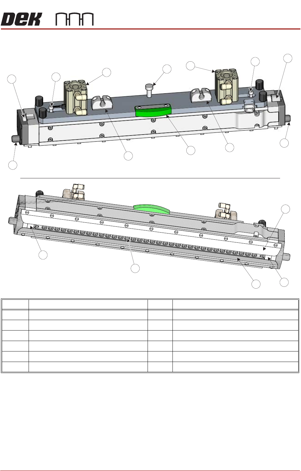
Transfer Head
The transfer head is a detachable assembly with a sealed twin chamber
configuration. This protects the print medium from the environment after it has
been pneumatically driven out of the paste cartridge.
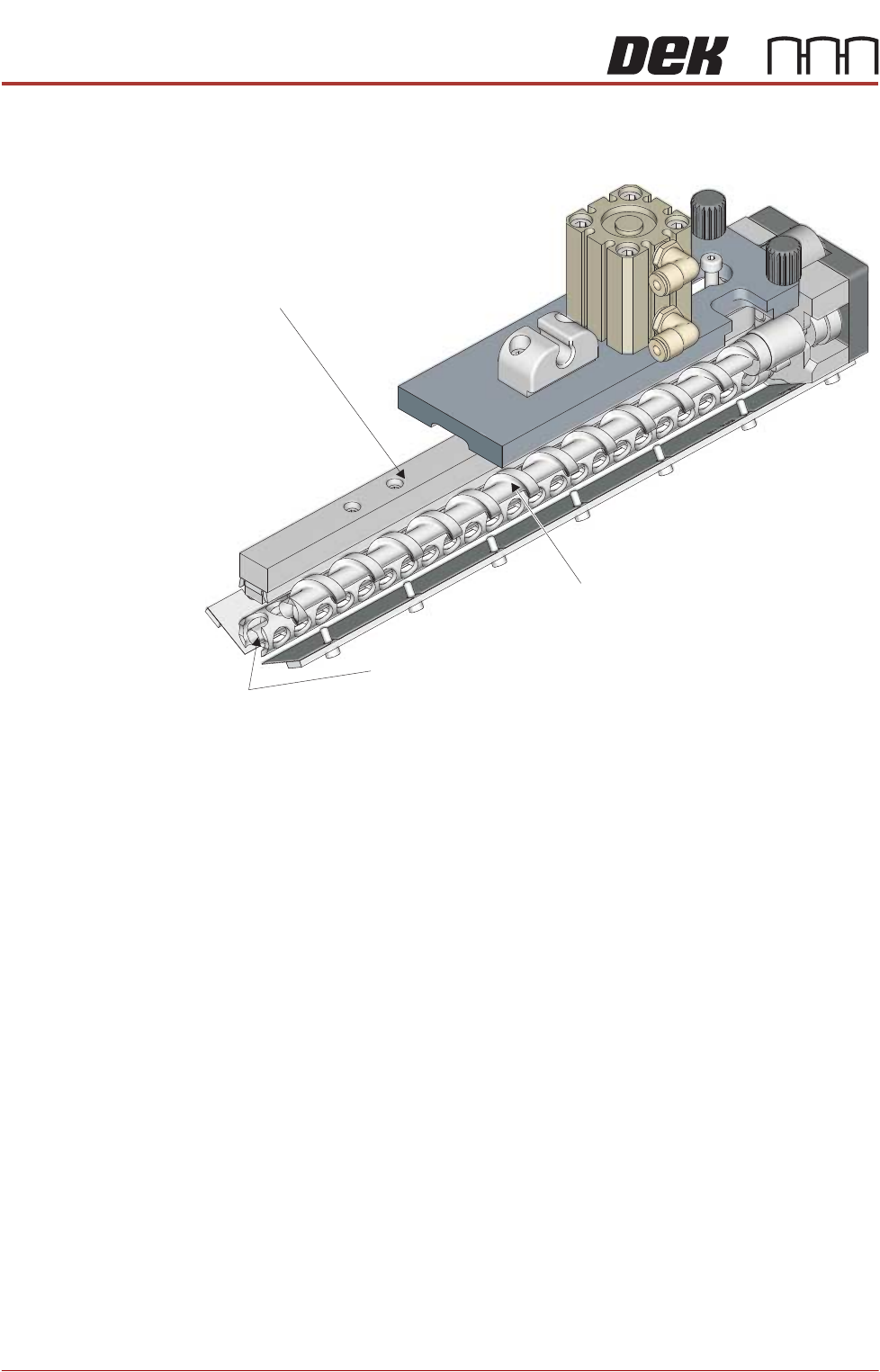
An Archimedes screw distributes the print medium along the length of the
conditioning chamber and a crosshead piston pushes down on it, providing a
pressurised environment. This, along with the rotating conditioning grid, pre-
pares the print medium for printing.
As the transfer head moves across the stencil, the print medium is forced
through the apertures in the stencil by a combination of the system pressure,
the print medium pressure, and the rolling action of the conditioning grid.
Item Description Item Description
1 Pin Mount 7 Print Medium Type Indicator
2 Print Medium Pneumatic Cylinder (2 positions) 8 Conditioning Grid Drive Gear
3 Print Medium Level Indicator Pin (2 positions) 9 Front Wiper Blade
4 Archimedes Screw Drive Gear 10 Side Ski (2 positions)
5 Locator Dowel (2 positions) 11 Rear Wiper Blade
6 Base Cover Mount (2 positions) 12 Conditioning Grid
4
3
3
2
1
5
5
11
12
9
10
10
View On Top
View On Underneath
7
6
6
8
2
PROFLOW ATX
OVERVIEW
12.4 Technical Reference Manual Chapter Issue 6, Jan 16
As the trailing wiper moves across the stencil, a shearing action collects any
remaining print medium.
Figure 12-2 Transfer Head Internal Mechanism
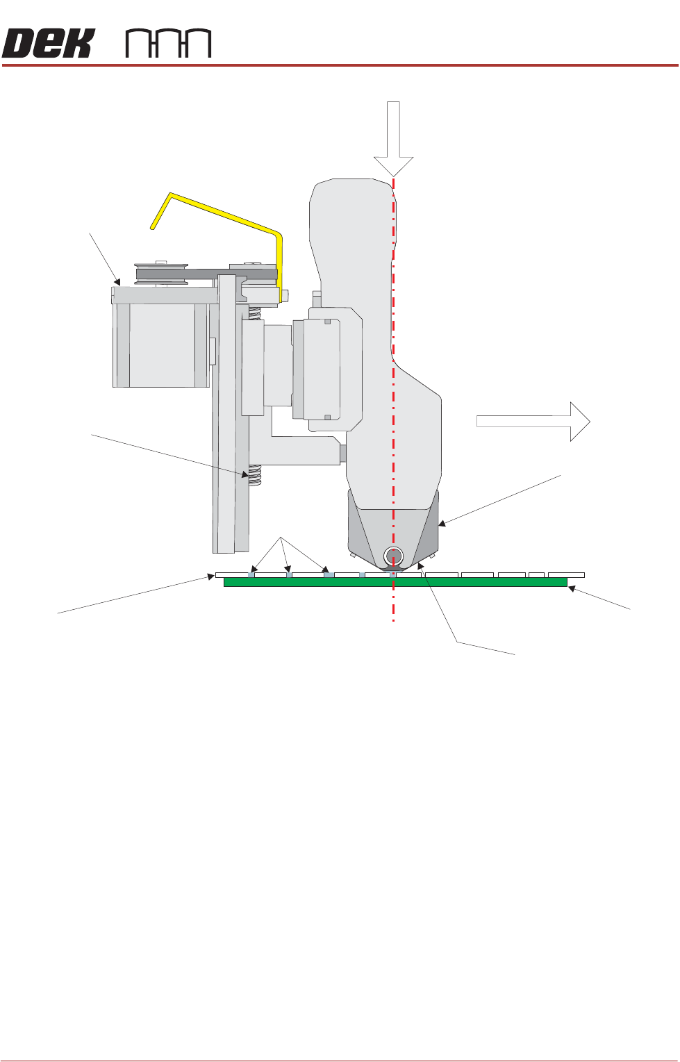
System Pressure The System Pressure is a programmable parameter that controls the contact
pressure of the transfer head against the stencil. As the transfer head moves
across the surface of the stencil, it must have enough downwards pressure to:
• Ensure that the side skis and wipers provide the enclosed environment
preventing any print medium leakage.
• Allow the trailing wiper to remove the excess print medium from the surface
of the stencil during printing.
The system pressure is maintained by a Z-axis stepper motor, which lowers and
raises the ProFlow ATx system. Based on a preset parameter, the motor turns
a leadscrew that precisely positions the transfer head’s wipers and skis against
the stencil.
NOTE
It is important for the transfer head to be aligned vertically to ensure that the
contact pressure on both wipers is equal.
View on Top (side and top sections cut away)
Crosshead Piston
Conditioning Grid
Archimedes Screw
PROFLOW ATX
OVERVIEW
Chapter Issue 6, Jan 16 Technical Reference Manual 12.5
ATx Movement (Y Axis)
Z-Axis System Pressure
Down Through Centre of
Transfer Head Unit
Transfer Head Unit
Print
Medium
Z Axis Motor
Z Axis Screw
View on Left Side
Stencil
Board
Wiper (2 Positions)