Printer 710-810 v9 ProFlow ATX.pdf - 第10页
PROFLOW ATX OVERVIEW 12.10 Technical Reference Manual Chapter Issue 6, Jan 16 With the base cover fitted and locked to the transfer head, a seal is created between the wiper blades, the side skis and the base cover . A t…
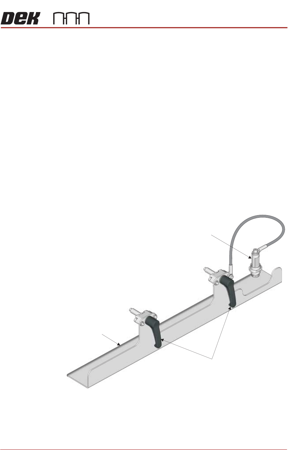
PROFLOW ATX
OVERVIEW
Chapter Issue 6, Jan 16 Technical Reference Manual 12.9
Transfer Head
Base Cover
The ProFlow ATx system has a base cover which is fitted to the base of the
transfer head to keep the print medium sealed during:
• Non-operation
• Fitting/Removal of the Transfer Head
• Temporary Storage
NOTE
Temporary storage time is dependent on the print medium used, see manufac-
turers recommendations. If storage time exceeds the recommendation, the
ProFlow transfer head must be emptied and cleaned.
The transfer head base cover:
• Prolongs the life of the print medium by sealing the transfer head
• Prevents the operator from coming into contact with the print medium when
removing or fitting the transfer head
• Prevents damage to the wiper blades and skis when removing or fitting the
transfer head
• Prevents print medium from dripping into the printer when removing or
fitting the transfer head
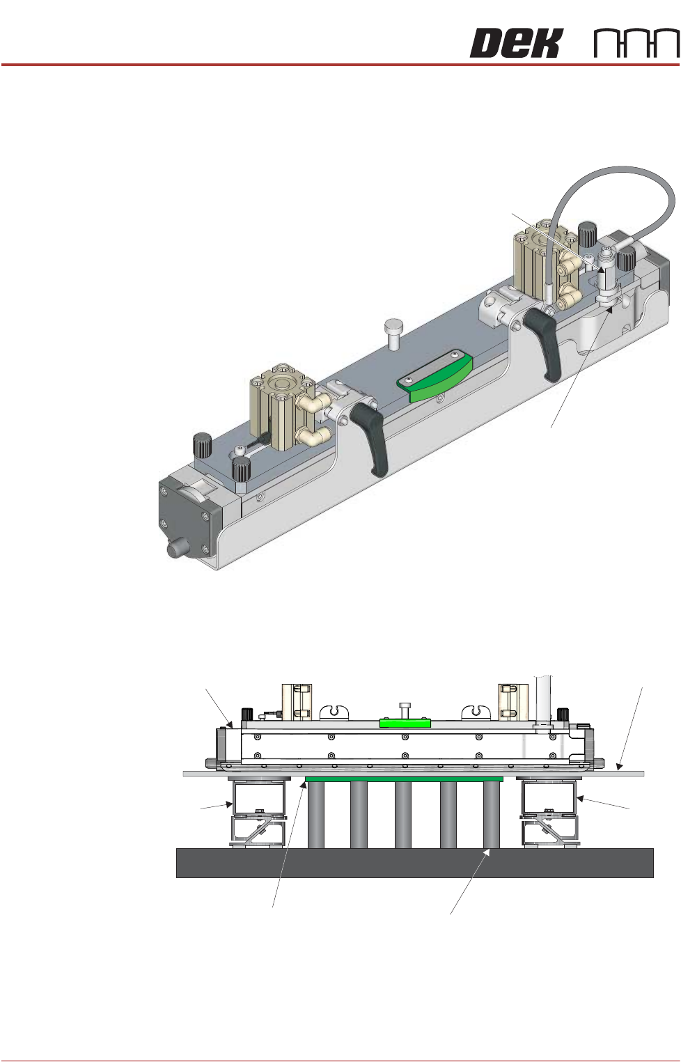
View on Front Left Corner
Base Cover
Locking Clips
Transfer Head Sealing Plug
PROFLOW ATX
OVERVIEW
12.10 Technical Reference Manual Chapter Issue 6, Jan 16
With the base cover fitted and locked to the transfer head, a seal is created
between the wiper blades, the side skis and the base cover. A transfer head
sealing plug is locked into the transfer head inlet, completing the seal and
protecting the print medium.
ProFlow ATx
Stencil Support
The ProFlow ATx stencil support option provides extra support for the stencil
when printing boards which are narrower than the transfer head. This extra
support prevents print medium smearing, and also the reduction of the pressure
within the transfer head.
View on Left Hand Front Corner
Transfer Head Inlet
Transfer Head Sealing Plug
Stencil
Transfer Head
Board
Rising Table
ProFlow
Stencil
Support
ProFlow
Stencil
Support
View on Front (ProFlow ATx Mount not Shown)
Magnetic Tooling Pin
PROFLOW ATX
ELECTRICAL SCHEMATIC
Chapter Issue 6, Jan 16 Technical Reference Manual 12.11
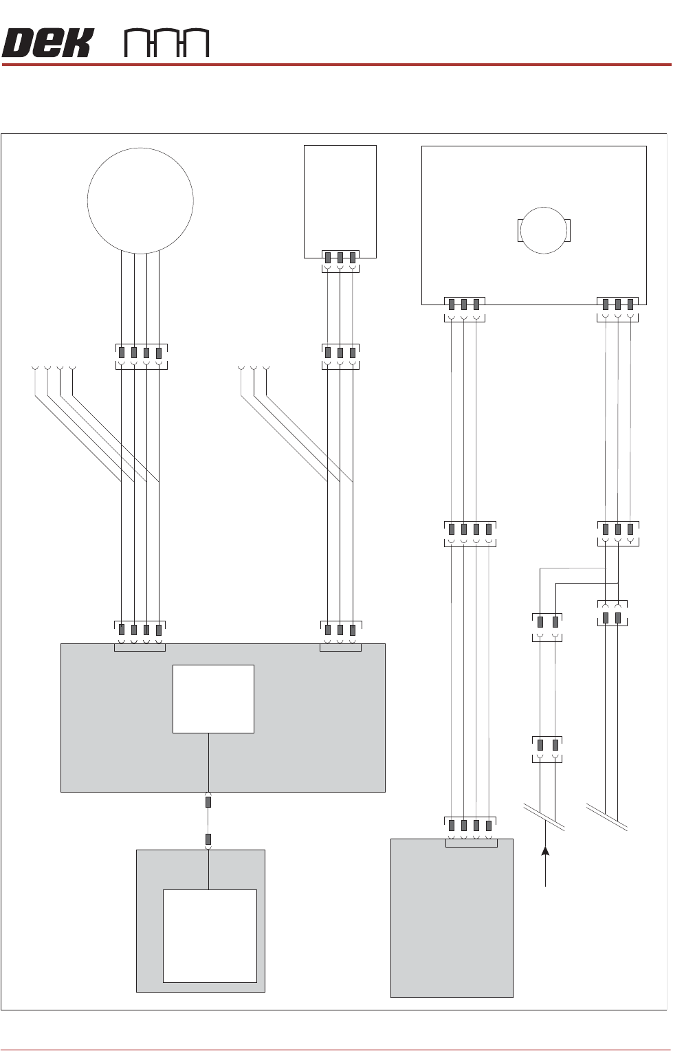
ELECTRICAL SCHEMATIC
Figure 12-5 Sheet 1
Motherboard
USB
Machine
Controller M36
NextMove
ES
Machine PC
Power Supply
Enclosure M37
9SK96
M37SK21
Conditioning Grid Motor
ProFlow Node 13
M
ProFlow Home
Solid State
Microswitch
Z-Axis
Stepper Motor
9M4
M36SK21
9SK12
3SK35
M36SK28
9SK17
CH 2 B-
CH 2 B+
CH 2A-
CH 2A+
9SK08
+12V
DIG IN 4
0V
M36SK12
N13SK01
+42/48V
0V Return
24V US (Motor Logic)
0V
N13SK02
9PL98
CAN_H
CAN_L
CAN_GND
9SK99
CAN In From
Rising Table Node 6
N3SK2
To Print Carriage Input/output
Node 3 (Continued on Page 2)
9PL95
9SK08
9SK17