Printer 710-810 v9 ProFlow ATX.pdf - 第43页
PROFLOW ATX REPLACEMENT PROCEDURES Chapter Issue 6, Jan 16 Technical Reference Manual 12.43 Replacing the Crosshead Piston Seal MANDA TOR Y T OXIC CHEMICALS MAY BE PRESENT. SAFETY GLOVES MUST BE WORN. MANDA TOR Y T OXIC …
PROFLOW ATX
REPLACEMENT PROCEDURES
12.42 Technical Reference Manual Chapter Issue 6, Jan 16
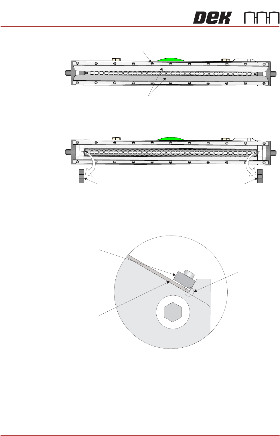
7. Using a flat bladed screwdriver, loosen the wiper blade retainer screws.
8. Remove the wiper blades (2 positions).
9. Remove the skis (2 positions).
10. Fit the new skis, ensuring that the tabs face inwards and the holes face
outwards.
11. Fit the wiper blades (under the retainers) ensuring each blade is seated
firmly against the transfer head along its whole length.
12. Tighten the wiper blade retainer screws.
Retainer Screw
Wiper Blades
Transfer Head Underside View
Transfer Head Underside View
SkiSki
View on End of Transfer Head
Wiper Blade
Contact Point
Wiper Blade
Wiper Blade
Retainer
PROFLOW ATX
REPLACEMENT PROCEDURES
Chapter Issue 6, Jan 16 Technical Reference Manual 12.43
Replacing the Crosshead Piston Seal
MANDATORY
TOXIC CHEMICALS MAY BE PRESENT. SAFETY GLOVES MUST BE WORN.
MANDATORY
TOXIC CHEMICALS MAY BE PRESENT. EYE PROTECTION MUST BE WORN.
To replace the crosshead piston seal, carry out the following:
1. Select Open Cover Commands.
2. Select Carriage to Front.
3. Open the machine cover.
4. Remove the print medium cartridge and filler tube assembly.
5. Remove the transfer head from the ProFlow ATx mount.
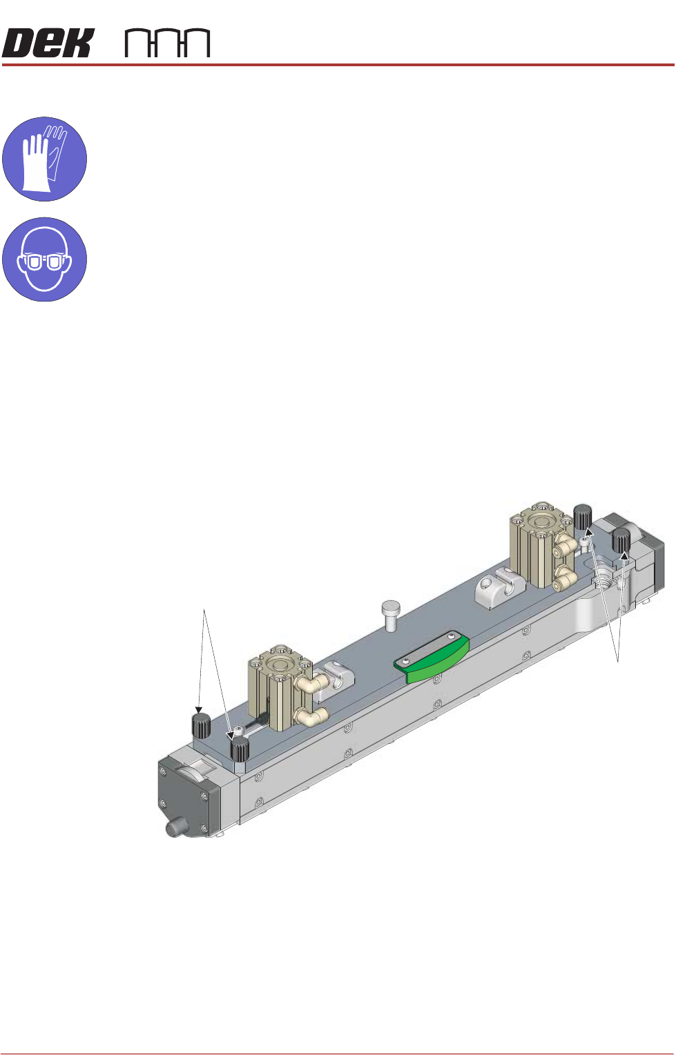
6. Loosen the four captive top plate securing screws.
Top Plate
Securing Screws
Top Plate
Securing Screws
View on top of the Transfer Head
PROFLOW ATX
REPLACEMENT PROCEDURES
12.44 Technical Reference Manual Chapter Issue 6, Jan 16
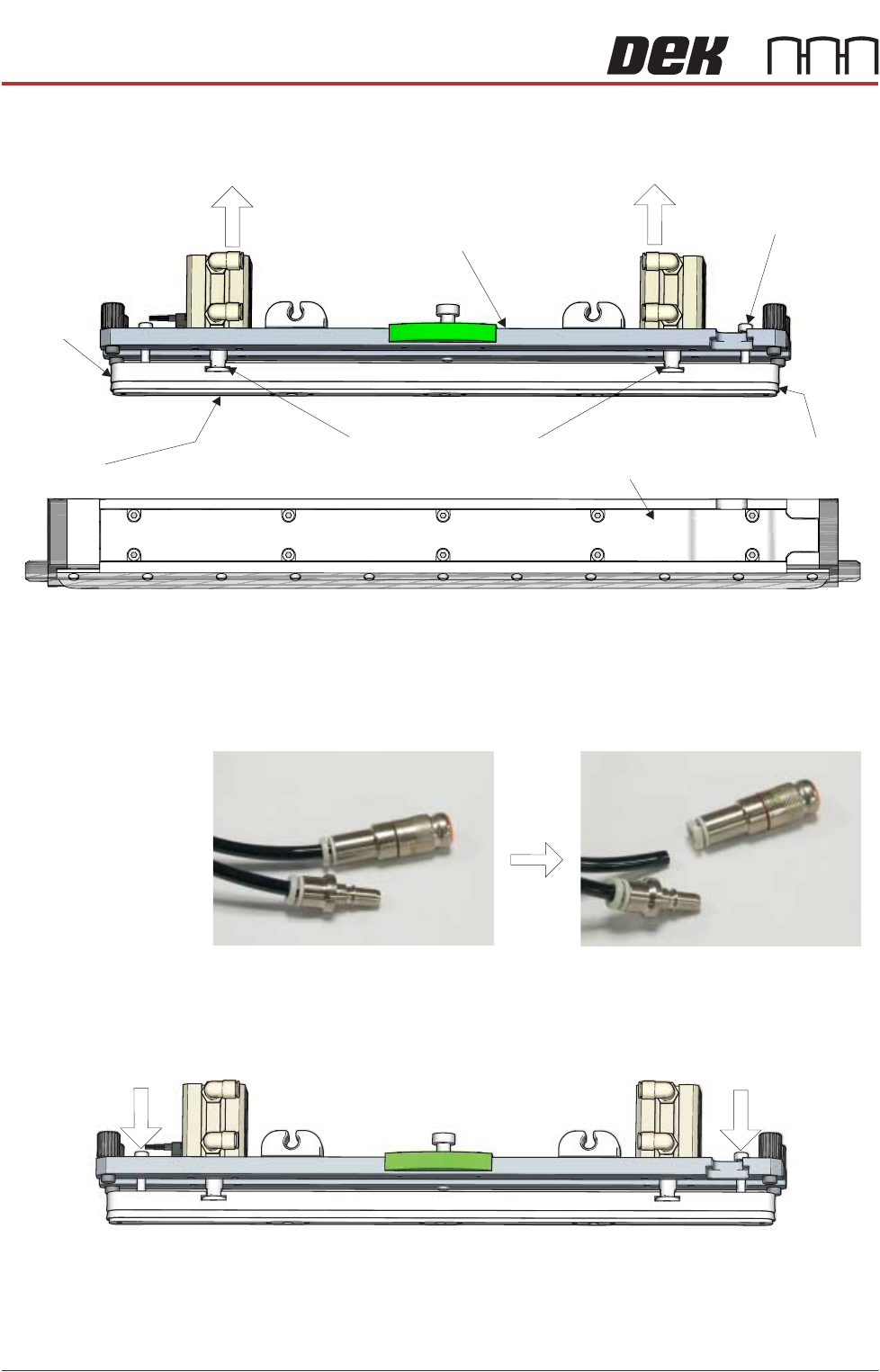
7. Separate the main body of the transfer head from the top plate and cross-
head piston assembly.
8. Remove the pneumatic connector from the crosshead piston’s down air feed
pipe; this allows easy movement of the crosshead piston pneumatic sole-
noids.
9. Push the crosshead piston away from the top plate (into its down position),
using the two print medium level indicator pins.
10. Refit the pneumatic connector onto the piston’s down air feed (to prevent
the piston from retracting back towards the top plate).
Transfer Head Main Body
Crosshead
Piston
Crosshead
Piston Seal
Crosshead Piston Shafts
View on Front of Transfer Head
Piston Seal
Retainer
Print Medium Level
Indicator (2 Positions)
Transfer Head
Top Plate
View on Piston Air Feed Pneumatic Connectors
Connector Attached to Pipe
Connector Disconnected from Pipe
Piston Up
Piston Down
View on Front of Transfer Head