Printer 710-810 v9 ProFlow ATX.pdf - 第8页
PROFLOW ATX OVERVIEW 12.8 Technical Reference Manual Chapter Issue 6, Jan 16 Figure 12-4 T ransfer Head Unit S t atus During Charging Action The Archimedes screw and conditioning gr id stop rotatin g, the system pressure…
PROFLOW ATX
OVERVIEW
Chapter Issue 6, Jan 16 Technical Reference Manual 12.7
Print Medium
Recharging
At the end of a print stroke, if the print medium demand sensor detects that the
print medium level is low, the ProFlow ATx system recharges the transfer head
from the print medium cartridge.
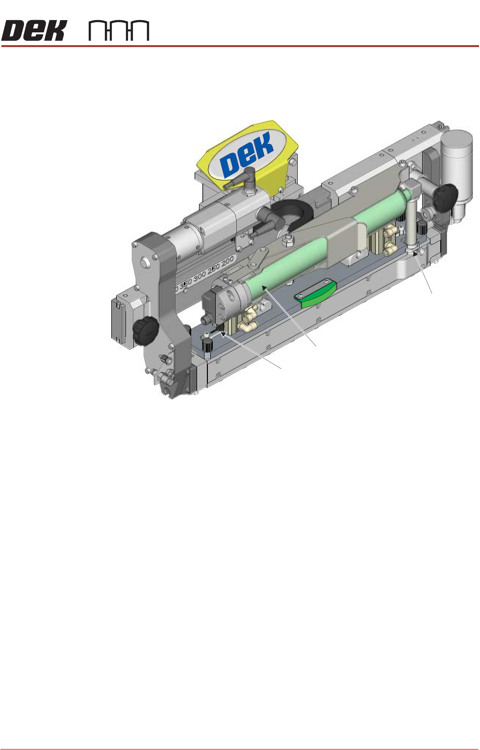
Figure 12-3 Demand Sensor
During the recharge process, the print rails remain raised to support the transfer
head, and system pressure is applied to the ProFlow ATx system to prevent any
leakage. The print medium pressure is released, raising the crosshead piston
and creating a void in the conditioning chamber. Pneumatic pressure is applied
to the print medium cartridge driving print medium to the transfer head inlet and
on to the Archimedes screw. The Archimedes screw rotates for a set period of
time delivering the print medium into the conditioning chamber. The rotating
conditioning grid prepares and distributes the print medium ready for applica-
tion.
View on Left Hand Front Corner
Print Medium Demand Sensor
Print Medium Cartridge
Transfer Head Inlet
PROFLOW ATX
OVERVIEW
12.8 Technical Reference Manual Chapter Issue 6, Jan 16
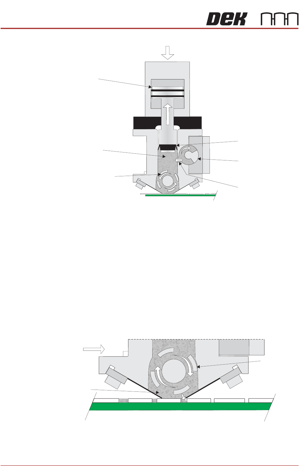
Figure 12-4 Transfer Head Unit Status During Charging Action
The Archimedes screw and conditioning grid stop rotating, the system pressure
is relaxed, and print medium idle pressure is applied.
NOTE
Recharging the transfer head is an automatic process and requires no interven-
tion from the machine operator.
Rolling Conditioning During recharging, the conditioning grid rotates. This action keeps the print
medium in the optimum condition required for successful printing.
During the print process the rotation of the conditioning grid, working together
with the print medium pressure, forces print medium into the apertures of the
stencil.
Cross Section on Left Hand Side of Transfer Head
Paste Pressure
Piston
Archimedes Screw
Conditioning
Grid
Crosshead Piston
System Pressure
Print
Medium
Inlet Port
Direction of
Print Carriage
Print
Medium
Cross Section on Left Hand Side of Transfer Head
Conditioning
Grid
PROFLOW ATX
OVERVIEW
Chapter Issue 6, Jan 16 Technical Reference Manual 12.9
Transfer Head
Base Cover
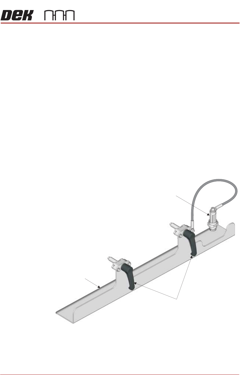
The ProFlow ATx system has a base cover which is fitted to the base of the
transfer head to keep the print medium sealed during:
• Non-operation
• Fitting/Removal of the Transfer Head
• Temporary Storage
NOTE
Temporary storage time is dependent on the print medium used, see manufac-
turers recommendations. If storage time exceeds the recommendation, the
ProFlow transfer head must be emptied and cleaned.
The transfer head base cover:
• Prolongs the life of the print medium by sealing the transfer head
• Prevents the operator from coming into contact with the print medium when
removing or fitting the transfer head
• Prevents damage to the wiper blades and skis when removing or fitting the
transfer head
• Prevents print medium from dripping into the printer when removing or
fitting the transfer head
View on Front Left Corner
Base Cover
Locking Clips
Transfer Head Sealing Plug