OM-1461-001_w.pdf - 第19页
16 7. Placement Head/Nozzle Data 0712-001 7. Placement Head/Nozzle Data When the [Stocker 3] tab is pressed in the "Placement Head/Nozzle Data" tab sheet, the following subtab sheet appears. Fig.7 "Stocker…
150712-001
6. Nozzle Change in the Manual Operation
Procedure
Procedure
• Procedure for Nozzle Storage
Notice
Do not perform any nozzle storage operation while a component
is picked up by the head. Otherwise, the vacuum will be turned off,
releasing the component from the head.
(1) Press the head (one of the head selection buttons) holding the nozzle
desired to be stored.
The background color of the selected button turns yellow.
(2) Select the nozzle (one of the nozzle allocation No. selection buttons)
holding the nozzle desired to be stored.
The background color of the selected button turns yellow.
(3) Select the address button of the nozzle stocker in which the nozzle
should be stored.
The background color of the selected button turns yellow.
(4) Press the [Reset Nozzle] button.
The background color of the button turns green and the selected
head selection button, nozzle allocation No. button, and nozzle
stocker address buttons are set active.
(5) When the [START] button of the operation panel is pressed, the
selected nozzle is stored in the selected nozzle stocker (located at
thespeciedaddress).
• Procedure for Nozzle Attachment
Notice
Be sure not to perform any nozzle attachment operation while the
head is holding a component.Otherwise, the vacuum will be turned
off, releasing the component from the head.
(1) Select the head (one of the head selection buttons) where the desired
nozzle should be attached.
The background color of the selected button turns yellow.
(2) Select the nozzle allocation No. button to specify the position where
the nozzle should be attached.
The background color of the selected button turns yellow.
(3) Select the address button of the nozzle stocker where the nozzle to
be attached is stored.
The background color of the selected button turns yellow.
(4) Press the [Set Nozzle] button.
The background color of the button turns green and the selected
head selection button, nozzle allocation No. button, and nozzle
stocker address buttons are set active.
(5) When the [START] button on the operation panel is pressed, the
speciednozzleisattached.
Note
No nozzle can be attached to any nozzle No. position where a nozzle is
already attached.
16
7. Placement Head/Nozzle Data
0712-001
7. Placement Head/Nozzle Data
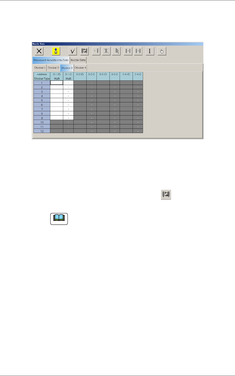
When the [Stocker 3] tab is pressed in the "Placement Head/Nozzle Data"
tab sheet, the following subtab sheet appears.
Fig.7 "Stocker3
"
Tab Sheet
Address Stocker Type
3-1 ID Multi
Set the IDs of the nozzles stored in the nozzle stocker.
When an arbitrary nozzle ID is selected and the " " icon is pressed,
the "Nozzle Type" window opens.
Note
Double-clicking a nozzle ID cell also opens the "Nozzle Type"
window.
3-1 C Multi
Thisfunctionisusedtodeterminewhetherthespotsspeciedinthe
nozzle stocker must be used or not (bypassed).
Enter "-" as a control command for normal use. To bypass a spot, enter
"S" in the corresponding text box.
17
8. Teaching
0712-001
8. Teaching
Note
This section is described by taking as an example the multi-functional head
attached to Head No. 3 position.
8.1 Head Rotation Angle Axis
This offset corrects the Z-phase positional deviation of the rotation axis for
each nozzle from the placement coordinate reference.
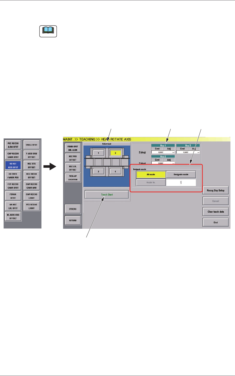
(1) When the [OTHERS] button is pressed on the "TEACHING" submenu
bar, the menu bar for the other teaching functions pops up.
(2) Press the [HD ROT AXIS OFST] button on the pop-up menu bar.
[1]
[2]
[3]
[4]
Fig.7-1 "HEAD ROTATE AXIS" Window
[1] Select Head Buttons
The button images showing the head positions are displayed. Using
these buttons, the head to be taught is selected.