OM-1461-001_w.pdf - 第21页
18 8.1 Head Rotation Angle Axis 0712-001 [2] "Nozzle Rotation Angle Axis" Display Section For the nozzle positions (No. 1 to No. 3) where the multi-functional nozzles are set, the offset data values for angle Z…
17
8. Teaching
0712-001
8. Teaching
Note
This section is described by taking as an example the multi-functional head
attached to Head No. 3 position.
8.1 Head Rotation Angle Axis
This offset corrects the Z-phase positional deviation of the rotation axis for
each nozzle from the placement coordinate reference.
(1) When the [OTHERS] button is pressed on the "TEACHING" submenu
bar, the menu bar for the other teaching functions pops up.
(2) Press the [HD ROT AXIS OFST] button on the pop-up menu bar.
[1]
[2]
[3]
[4]
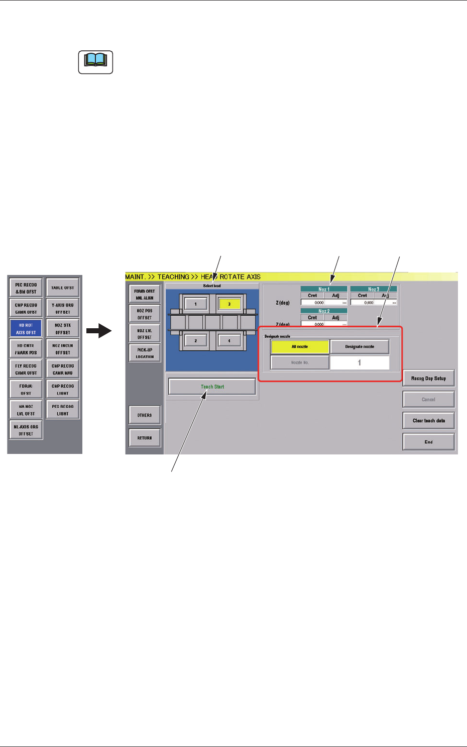
Fig.7-1 "HEAD ROTATE AXIS" Window
[1] Select Head Buttons
The button images showing the head positions are displayed. Using
these buttons, the head to be taught is selected.

18
8.1 Head Rotation Angle Axis
0712-001
[2] "Nozzle Rotation Angle Axis" Display Section
For the nozzle positions (No. 1 to No. 3) where the multi-functional
nozzles are set, the offset data values for angle Z (°) created by the PCB
locating coordinate system and camera coordinate system are displayed.
Cmt
: Offset values before teaching
Adj
: Offset values obtained as the result of teaching
[3] [Designate nozzle] Button and Nozzle Display Section
Using these selection buttons, the nozzle to be taught is designated.
When the [Designate Nozzle] button is pressed, the "Designate Nozzle"
window appears.
[4] Operation Button
[Teach Start] Button
Using this button, the teaching is executed.
•
Teaching Procedure
Procedure
(1) Select the multi-functional head where the head rotation angle
offset is to be taught.
(2) Press the [Designate nozzle] button for the head to be used, and
select the nozzle to be taught in the displayed "Nozzle Selection"
window.
(3) Press the [Teach Start] button.
Thedesignatedbeamwillmovetothepositionspeciedandthe
head rotation angle offset is taught.
•
When the teaching is begun, the start-up conditions are
checked.
•
If any recognition error occurs in the course of the teaching,
or the [STOP] button is pressed on the operation panel, the
operation is paused. From this condition, re-start is available.
•
In the pause condition, no other menu can be selected.
When the teaching is completed, the designated head is returned
to the origin automatically. The teaching results are displayed in
the"BeamXYOffsetConrmation"displaysection.
19
8.2 Head Rotation Center Offset/Basis Mark Position Teaching
0712-001
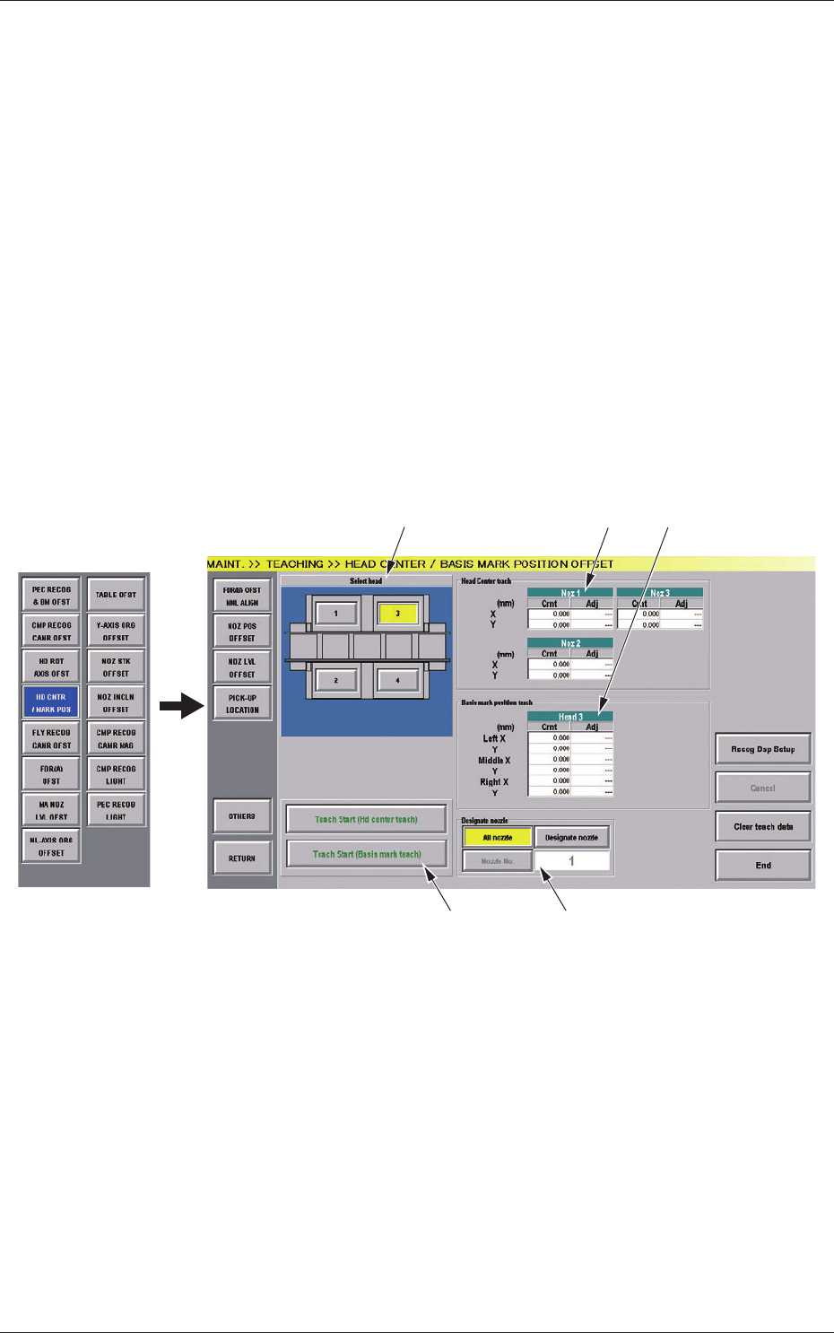
8.2 Head Rotation Center Offset/Basis Mark Position
Teaching
By means of recognizing the pattern printed on the jig component (QFP
Glass Plate Jig) picked up by the nozzle, using the component recognition
camera at the angles of 0°, 90°, 180° and 270°, the offset data is taught,
which corrects the deviation of the head rotation center and PEC recognition
camera center from the reference values.
Also, the basis mark position shot using the PEC recognition camera,
is taught, when the head rotation center is moved onto the component
recognition camera view.
(1) When the [OTHERS] button is pressed on the "TEACHING" submenu
bar, the menu bar for the other teaching functions pops up.
(2) Press the [HD CNTR / MARK POS] button on the pop-up menu bar.
[1] [2] [3]
[4] [5]
Fig.7-2 "HEAD CENTER / BASIS MARK POSITION OFFSET" Window