OM-1461-001_w.pdf - 第25页
22 0712-001 • Rotation Angle Z-axis Angle Deviation Fig.7-3 8.2 Head Rotation Center Offset/Basis Mark Position T eaching

210712-001
•
Teaching Procedure
Procedure
(1) Replace the nozzle with the jig nozzle before the teaching and
place the QFP Glass Plate Jig in the jig storage space on the
component recognition camera.
Place the QFP Glass Plate Jig with its printed surface turned
down.
(2) Select the multi-functional head where the head rotation center/
basis mark position is taught.
(3) Press the [Teach Start (Hd center teach)] button. The head
rotation center offset will be taught.
•
When the teaching is begun, the start-up conditions are
checked.
•
If any recognition error occurs in the course of the teaching,
or the [STOP] button is pressed on the operation panel, the
operation is paused. From this condition, re-start is available.
•
In the pause condition, no other menu can be selected.
When the teaching is completed, the designated head is
returned to the origin automatically.
The teaching results are displayed in the "Head Center teach"
display section.
(4) Press the [Teach Start (Basis mark teach)] button.
The basis mark offset is taught.
•
When the teaching is begun, the start-up conditions are
checked.
•
If any recognition error occurs in the course of the teaching,
or the [STOP] button is pressed on the operation panel, the
operation is paused. From this condition, re-start is available.
•
In the pause condition, no other menu can be selected.
When the teaching is completed, the designated head is returned
to the origin automatically. The teaching results are displayed in
the "Basis mark position teach" display section.
(5) When the teaching is completed, remove the QFP Glass Plate Jig.
8.2 Head Rotation Center Offset/Basis Mark Position Teaching

220712-001
•
Rotation Angle
Z-axis Angle Deviation
Fig.7-3
8.2 Head Rotation Center Offset/Basis Mark Position Teaching
230712-001
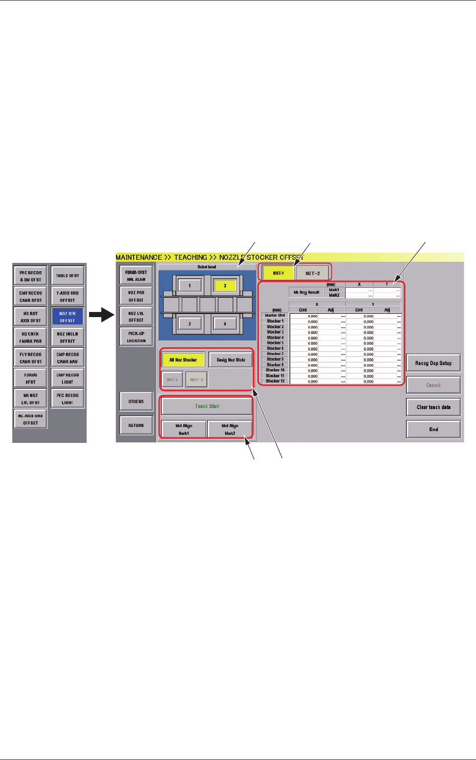
8.3 Nozzle Stocker Offset
8.3 Nozzle Stocker Offset
This procedure teaches the offset to secure the nozzle stocker position
(machine coordinate reference). The inclination in direction X from the
recognition mark for the recognized nozzle stocker section, is calculated
andthevaluesarereectedautomaticallyonthenozzlestockeroffsetin
directions X and Y.
(1) When the [OTHERS] button is pressed on the "TEACHING"
submenu bar, the menu bar for the other teaching functions pops
up.
(2) Press the [NOZ STK OFFSET] button on the pop-up menu bar.
[5]
[1]
[2]
[3]
[4]
Fig.7-4 "NOZZLE STOCKER OFFSET" Window
[1] Select Head Button
The button images showing the head positions are displayed.
Using these images, the PEC recognition camera to be used in the
teaching, is selected.
[2] Nozzle Stocker Select Button
[NST-1], [NST-2] Button
Pressing the [NST-1] or [NST-2] selects the nozzle stocker for which
the offset is displayed.