OM-1461-001_w.pdf - 第80页
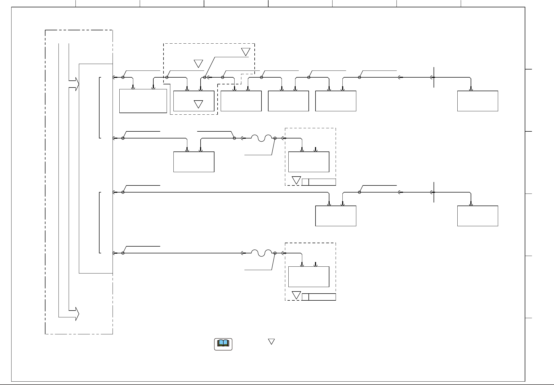
77 0712-001-(M845JA-A1038) CPU2-R Cable Connection (HLS) -U85 HLSB-PCI -X0801 -X0802 UB32(T ransfer) -X0902 UB32 (Cutter Positioning, Rear) UB32 (Cutter Positioning, Front) -X0101 -X0102 UB32 (Operation Panel, Front) CN1…
76
CN1
-X0501
-X0502 -X0704 -X0705
UB43
(Input / Output Machines)
-X0801 -X0802
UB32
(Transfer)
-X0902
UB32
(Cutter Positioning, Rear)
UB32
(Cutter Positioning, Front)
CN1
CN2
CH1
CH2
CN4
CN3
CN2
CN5CN4
CN2A/2BCN1A/1B CN2A/2BCN1A/1B
CN2A/2BCN1A/1B
-X20201
SCR
D-sub_9P
SCR SCR
SCR
RJ45
RJ45
RJ45
-U07 -U08 -U09
-X10306
-X0901
-X20201
D-sub
9P
RJ45
D-sub_9P
-U69
RJ45
CN80
UB34(Feeder Base)
-X6980
-X30
-X1300B
-X1300B
-X30
-X6980
UB34(Feeder Base)
CN80
RJ45
-U69
-U85
HLSB-PCI
-U09
-X0902-X0901
-X0101 -X0102
UB32
(Operation Panel, Rear)
CN2A/2BCN1A/1B
SCR
-U01
UB13(Head I/O)
-X1701
-U17
-U05
-X1603 -X1604
UA54(ILB)
CN4CN3
-U16
D-sub
9P
(-X11604)
(-X0502)
-X1702
CN2A/2BCN1A/1B
U
UB13(Head I/O)
-X1701
-U17
-X1702
CN2A/2BCN1A/1B
U
HM-G300(1)
HM-G300(2)
-X10306
UB64
1 2 3 4 5 6 7 8
A
B
C
D
E
F
BL)S951 DX)S752
630 154 0696
DX)S753
630 157 7364
BL)S953
630 158 6649
C-)S252
C-)S252
630 158 6649
<ROBOT CABLE>
<ROBOT CABLE>
(0.5m)(0.7m)(2.3m)(1.5m)
(3.0m)
DX)S754
630 157 7371
(0.6m)
DX)S755
630 154 0726
(3.5m)
630 150 5466
630 150 5473
630 150 5848
BA)S951
BL)S954 (3.5m)
630 154 1945
BL)S952 (3.5m)
630 1505800
BA)S983
630 157 7357
(1.0m)
630 158 9282
BA)SA151
630 158 9312
BA)SA152 (0.3m)
(0.3m)
S
Note b
Note b
S
S
S
S
The Mark " " shows the connection document for your reference when
the multi-functional heads are mounted on the Block 1 or Block 2.
(a)
The cables are shown on the unit name of HM-G300 (multi-functional head)
side on the diagram.
(b)
S
Note
0712-001-(M845JA-A1037)
CPU2-L Cable Connection (HLS)
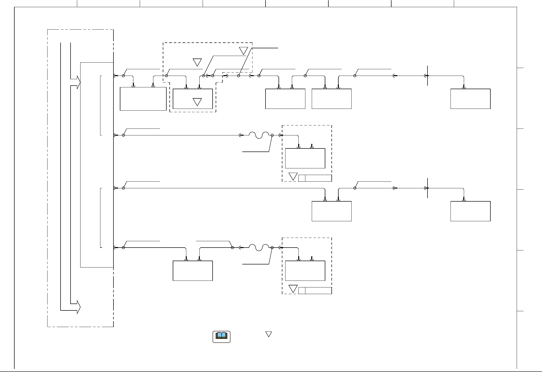
77
0712-001-(M845JA-A1038)
CPU2-R Cable Connection (HLS)
-U85
HLSB-PCI
-X0801 -X0802
UB32(Transfer)
-X0902
UB32
(Cutter Positioning, Rear)
UB32
(Cutter Positioning, Front)
-X0101 -X0102
UB32
(Operation Panel, Front)
CN1
CN2
CH1
CH2
CN4
CN3
CN2A/2BCN1A/1B CN2A/2BCN1A/1B
CN2A/2BCN1A/1B
CN2A/2BCN1A/1B
-X20201
D-sub_9P
SCR SCR
SCR
SCR
RJ45
RJ45
RJ45
-U08 -U09
-X0901
-X20201
RJ45
D-sub_9P
-U69
RJ45
CN80
UB34(Feeder Base)
-X6980
-X30
-X1300B
-X1300B
-X30
-X6980
UB34(Feeder Base)
CN80
RJ45
-U69
-U09
-X0902-X0901
-U01
CN1
-X0501
-X0502
CN2
SCR
-U05
-X1603 -X1604
UA54(ILB)
CN4CN3
-U16
D-sub
9P
(-X11604)
(-X0502)
UB13(Head I/O)
-X1701
-U17
-X1702
CN2A/2BCN1A/1B
U HM-G300(3)
UB13(Head I/O)
-X1701
-U17
-X1702
CN2A/2BCN1A/1B
U HM-G300(4)
-X10306
-X10306
(Note 2)
1 2 3 4 5 6 7 8
A
B
C
D
E
F
DX)S753
630 157 7364
BR)S954 BC)S983
630 157 7357
BR)S952
<ROBOT CABLE>
<ROBOT CABLE>
(0.5m)
(4.0m)
(3.5m) (1.0m)
DX)S756
630 154 0733
(3.5m)
DX)S757
1GG4W20041740
(0.6m)
630 154 1952
630 150 5855
BR)S951
BR)S953
(1.5m)
(3.0m)
630 150 5466
630 150 5848
(2.3m)
630 1505473
BC)S951
DX)S751 (0.3m)
630 154 7589
DX)S752
630 154 0696
(0.7m)
C-)S252
C-)S252
630 158 9282
BA)SA151 (0.3m)
630 158 9312
BA)SA152 (0.3m)
630 158 6649
1GG4W20042800
UB64
S
S
S
S
Note b
S
The Mark " " shows the connection document for your reference when
the multi-functional heads are mounted on the Block 3 or Block 4.
(a)
The cables are shown on the unit name of HM-G300 (multi-functional head)
side on the diagram.
(b)
S
Note
78
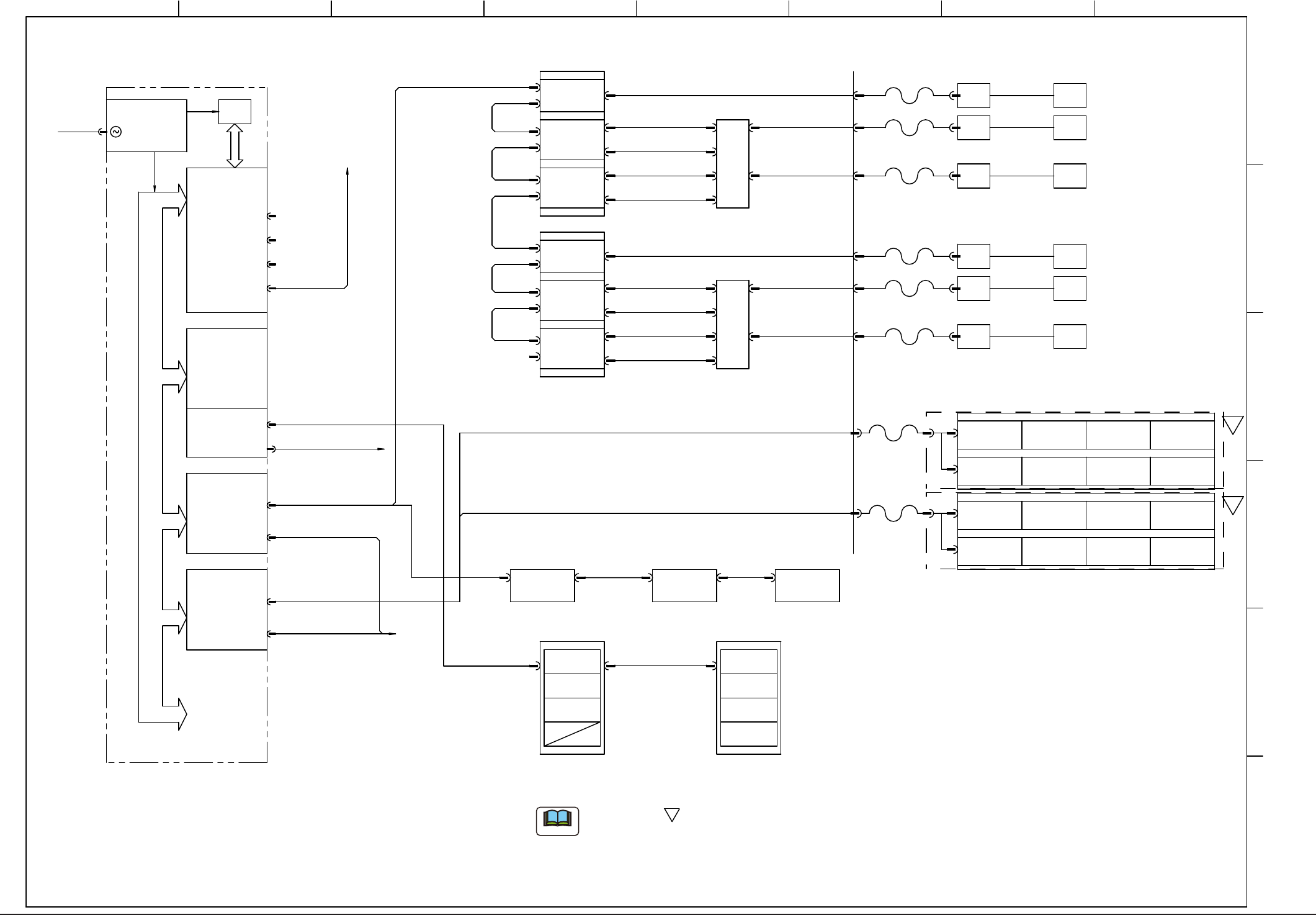
0712-001-(M845JA-A1039)
CPU2-L Cable Connection (SSCNET,AELINK)
To HUB(U72)
N.C.
N.C.
N.C.
I/O
(6-Axis x2ch)
SSCNET
MR-MC10
-U83
-U82
MR-MC10
SSCNET
(6-Axis x2ch)
I/O
MCIO-PCI
-U85
Pulsing
AE-LINK
HLSC
CN1
CN3
<Connector Relay Panel in Beam Section>
630 153 3049
BA)S956 (0.2M)
BA)S957 (0.2M)
BA)S958 (3.0M)
BA)S956 (0.2M)
BA)S957 (0.2M)
BA)S964 (2.0M)
630 154 030663
BA)965 (0.4M)
BA)S969 (0.4M)
BA)S967 (0.4M)
BA)S970 (0.4M)
BA)S966 (2.0M)
630 154 0313
BA)S968 (2.0M)
630 154 0320
BA)S952 (2.0M)
630 150 5428
BA)954 (3.5M)
630 150 8221
BA)S953 (2.0M)
630 1505435
BA)S960 (0.2M)
630 157 7463
BL)S955 (1.2M)
630 150 6142
BL)S956 (0.3M)
630 150 6159
FB)S157 VM0303B
630 108 1861
BA)S959 (0.4M)
630 153 3063
BA)S955 (3.0M,3.5M)
630 154 0306
630 154 0313
630 154 0320
BA)S964 (2.0M)
BA)965 (0.4M)
BA)S969 (0.4M)
BA)S967 (0.4M)
BA)S970 (0.4M)
BA)S966 (2.0M)
BA)S968 (2.0M)
630 156 8980
BL)S966 (2.0M)
630 157 7425
630 157 7432
630 157 7449
630 157 7425
630 157 7432
630 157 7494
630 157 7517
630 157 7500
630 157 7524
630 157 7494
630 157 7517
630 1577500
630 157 7524
<RobotCable>
<RobotCable>
<RobotCable>
<RobotCable>
<RobotCable>
<RobotCable>
<RobotCable>
<RobotCable>
NA
-A53
[6]
[5]
[4]
[3]
[2]
[1]
-A23
-U23
-A21
-U22-A22
UB18
-A21
-A23
-A22 -U22
-U23
UB18
CA
CA
CA
CB
CB
CB
[1]
-U21
-U21
CA
-U24
-U24
CB
DB(A)
-A63
[5]
-A63
DB(B)
[6]
-A41
[2]
[1]
[3]
[4]
-A51
[2]
[1]
[3]
[4]
-A145
-A145
[1] [2] [3] [4]
[1] [2] [3] [4]
[6][-][-][5]
-A141
-A141
[6][-][-][5]
SDD
PCI BUS
-U81
CPU2-L
+5V
(-5V)
-12V+5V
+3.3V
+12V
10/100
BASE-T
COM1
/MS
KBD
VGA
AC200V
-X8201
Backup 1
Conveyor A
Linear
Encoder
Linear
Encoder
Linear
Encoder
Linear
Encoder
Linear
Encoder
Linear
Encoder
Converter
Converter
Converter
Converter
Converter
Converter
-X8301
Beam X
Beam Y1
Beam Y2
Beam X
Beam Y1
Beam Y2
-X211A
-X211B
-X221A
-X221B
-X231B
-X231A
-X211A
-X211B
-X221A
-X221B
-X231A
-X231B
-X2102
-X2202
-X2302
-X2402
-X2403
-X2401
-X2404
-X12201
-X12301
-X12102 -U21
-U22
-U23
-X2102
-X2202
-X2302 -X2403
-X2402
-X2404
-X2401
-X12301
-X12201
-X12102
-X531A
-X187C1
-X187C1
-X8203
-X8303
-U23
-U22
-U21
Cutter (A)
-X631B-X631A
-X631A
Cutter (B)
-X2406-X2203
-X2303 -X2407
-X2203 -X2406
-X2303 -X2407
To UB64L
N1 N1N2
Conveyor L
Transfer
TransferL1
Conveyor A
TransferL1
ConveyorB
Conveyor Width 1
Conveyor L
Conveyor Width 2
Conveyor L
Conveyor Width 1
Conveyor B
Conveyor Width 2
Conveyor B
TB(24V)
-X531B
-X8511
-X8513
-X1411A
-X1451A
-X1411A
Nozzle 1
MD-Z1
Nozzle Rotation Nozzle Rotation
MD-Z2
Nozzle 2
Nozzle U/D
MD-L1
Nozzle 1 Nozzle 2
MD-L2
Nozzle U/D
MD-L3MD-Z3
Nozzle 1
MC-Z1
Nozzle Rotation Nozzle Rotation
MC-Z2
Nozzle 2
Nozzle U/D
MC-L1
Nozzle 1 Nozzle 2
MC-L2
Nozzle U/D
Nozzle U/D
MC-L3
Nozzle 3
VacantVacant
Nozzle Rotation
MC-Z3
Nozzle 3
-X1311A
-X1311A
-X1451A
Nozzle U/D
Nozzle 3
VacantVacant
Nozzle Rotation
Nozzle 3
1 2 3 4 5 6 7 8
A
B
C
D
E
F
S
S
Note b
The Mark " " shows the connection document for your reference when
the multi-functional heads are mounted on the Block 3 or Block 4.
(a)
The cable between the connectors [X1311A], [X1411A] and [X1451A] is
shown on the side of the unit name of HM-G300 (multi-functional head)
side on the diagram.
(b)
S
Note