OM-1461-001_w.pdf - 第20页
17 8. T eaching 0712-001 8. T eaching Note This section is described by taking as an example the multi-functiona l head attached to Head No. 3 position. 8.1 Head Rotation Angle Axis This offset corrects the Z-phase posit…
16
7. Placement Head/Nozzle Data
0712-001
7. Placement Head/Nozzle Data
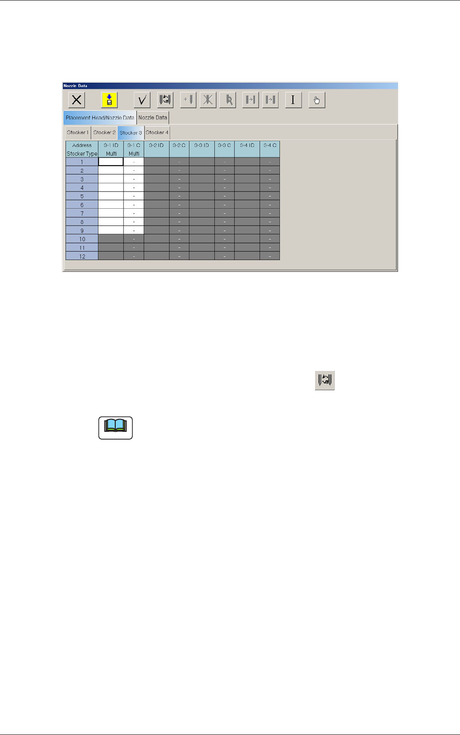
When the [Stocker 3] tab is pressed in the "Placement Head/Nozzle Data"
tab sheet, the following subtab sheet appears.
Fig.7 "Stocker3
"
Tab Sheet
Address Stocker Type
3-1 ID Multi
Set the IDs of the nozzles stored in the nozzle stocker.
When an arbitrary nozzle ID is selected and the " " icon is pressed,
the "Nozzle Type" window opens.
Note
Double-clicking a nozzle ID cell also opens the "Nozzle Type"
window.
3-1 C Multi
Thisfunctionisusedtodeterminewhetherthespotsspeciedinthe
nozzle stocker must be used or not (bypassed).
Enter "-" as a control command for normal use. To bypass a spot, enter
"S" in the corresponding text box.
17
8. Teaching
0712-001
8. Teaching
Note
This section is described by taking as an example the multi-functional head
attached to Head No. 3 position.
8.1 Head Rotation Angle Axis
This offset corrects the Z-phase positional deviation of the rotation axis for
each nozzle from the placement coordinate reference.
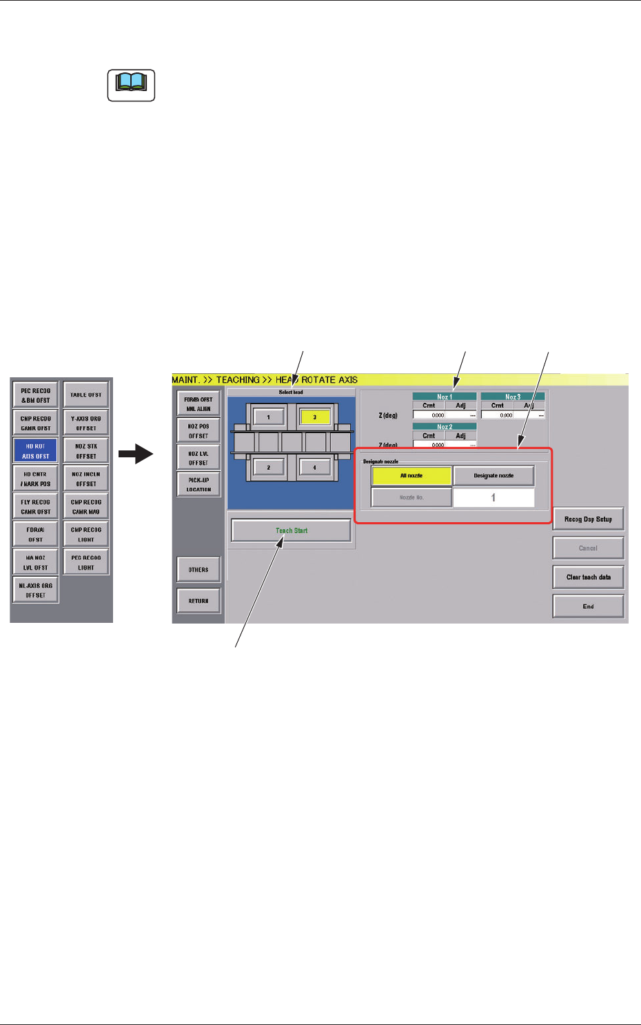
(1) When the [OTHERS] button is pressed on the "TEACHING" submenu
bar, the menu bar for the other teaching functions pops up.
(2) Press the [HD ROT AXIS OFST] button on the pop-up menu bar.
[1]
[2]
[3]
[4]
Fig.7-1 "HEAD ROTATE AXIS" Window
[1] Select Head Buttons
The button images showing the head positions are displayed. Using
these buttons, the head to be taught is selected.

18
8.1 Head Rotation Angle Axis
0712-001
[2] "Nozzle Rotation Angle Axis" Display Section
For the nozzle positions (No. 1 to No. 3) where the multi-functional
nozzles are set, the offset data values for angle Z (°) created by the PCB
locating coordinate system and camera coordinate system are displayed.
Cmt
: Offset values before teaching
Adj
: Offset values obtained as the result of teaching
[3] [Designate nozzle] Button and Nozzle Display Section
Using these selection buttons, the nozzle to be taught is designated.
When the [Designate Nozzle] button is pressed, the "Designate Nozzle"
window appears.
[4] Operation Button
[Teach Start] Button
Using this button, the teaching is executed.
•
Teaching Procedure
Procedure
(1) Select the multi-functional head where the head rotation angle
offset is to be taught.
(2) Press the [Designate nozzle] button for the head to be used, and
select the nozzle to be taught in the displayed "Nozzle Selection"
window.
(3) Press the [Teach Start] button.
Thedesignatedbeamwillmovetothepositionspeciedandthe
head rotation angle offset is taught.
•
When the teaching is begun, the start-up conditions are
checked.
•
If any recognition error occurs in the course of the teaching,
or the [STOP] button is pressed on the operation panel, the
operation is paused. From this condition, re-start is available.
•
In the pause condition, no other menu can be selected.
When the teaching is completed, the designated head is returned
to the origin automatically. The teaching results are displayed in
the"BeamXYOffsetConrmation"displaysection.