OM-1461-001_w.pdf - 第31页
28 0712-001 8.4 Head Nozzle Inclination Offset By means of recognizing the jig component (QFP Glass Plate Jig) picked up by using the nozzle, at angles of 0°, 90°, 180° and 270° using the component recognition camera, th…
270712-001
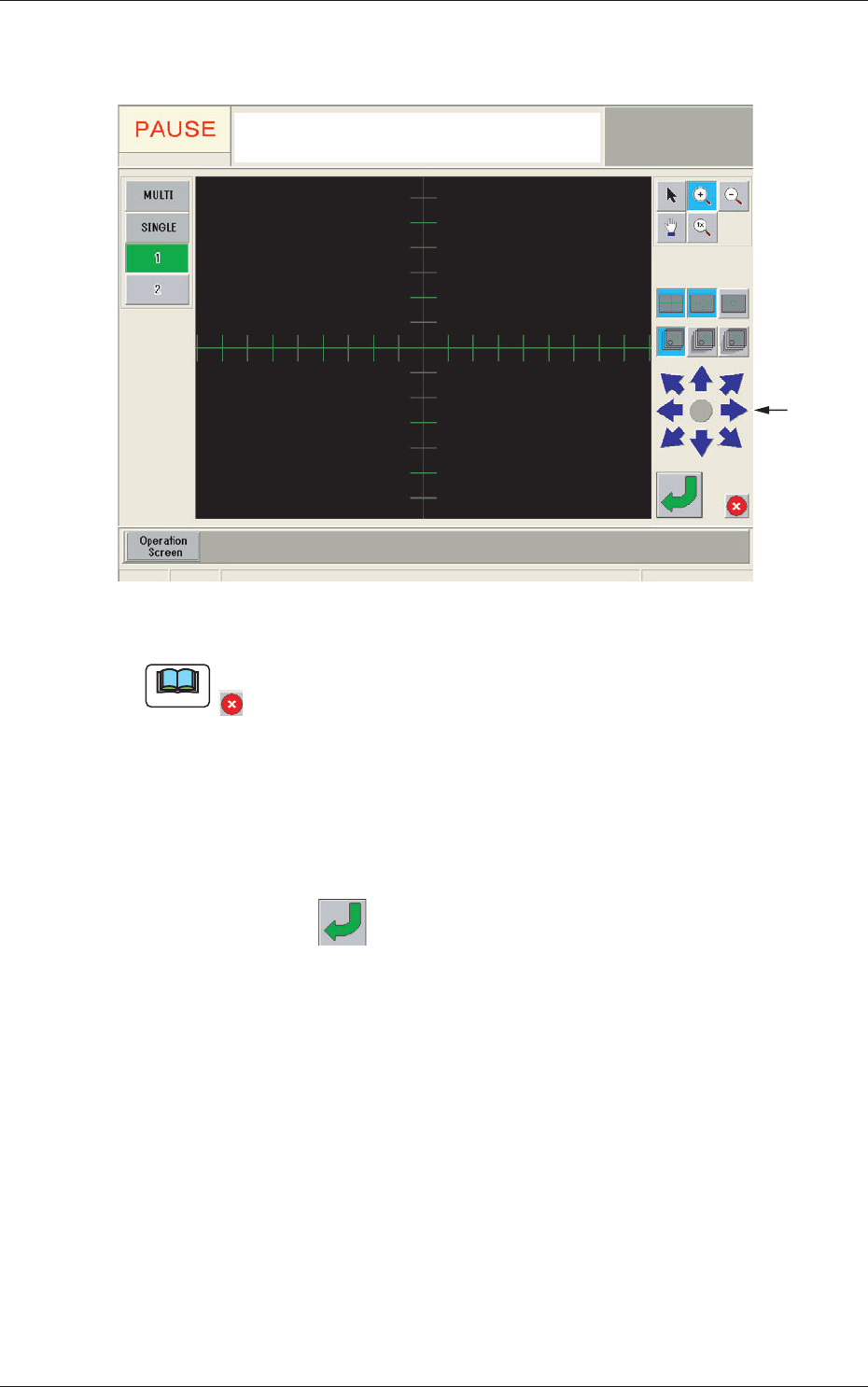
(2) When the [Mnl Align] button is pressed, the recognition window
appears and manual alignment operation is enabled.
Image
Moving
Buttons
Fig. 7-6 Recognition Window
Note
If the jig mark to be aligned manually is not in the camera view, press the
button in the recognition window to return to the "Manual Alignment
Operation Guide" window and move the beam.
(3) Move the jig mark to be aligned manually, using the image
moving buttons in the "Recognition" window, so that it is located
on the center of the cross lines.
(4) Press the
button in the "Recognition" window to secure the
location.
The "Recognition" window will be closed and the "NOZZLE
STOCKER OFFSET" window be returned.
(5) The teaching results are displayed in the "Offset" display section
in the "NOZZLE STOCKER OFFSET" window.
8.3 Nozzle Stocker Offset
280712-001
8.4 Head Nozzle Inclination Offset
By means of recognizing the jig component (QFP Glass Plate Jig) picked up
by using the nozzle, at angles of 0°, 90°, 180° and 270° using the component
recognition camera, the offset data is taught to correct the inclination of the
head nozzle.
Note
When the machine is delivered, such data has been adjusted and set.
Therefore, usually the offset teaching operation is not required.
(1) When the [OTHERS] button is pressed on the "TEACHING"
submenu bar, the menu bar for the other teaching functions is
popped up.
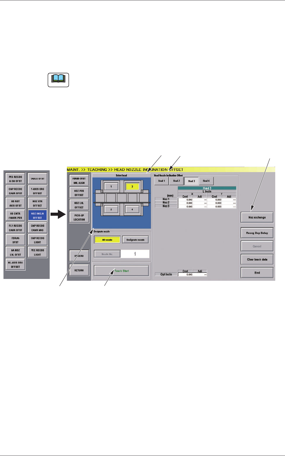
(2) Press the [NOZ INCLN OFFSET] button in the pop-up menu bar.
[2]
[1]
[3]
[4]
[5]
Fig.7-7 "HEAD NOZZLE INCLINATION OFFSET" Window
8.4 Head Nozzle Inclination Offset

290712-001
[1] Select Head Button
The button images showing the head positions are displayed.
Using these buttons, the PEC recognition camera used for the teaching
is selected.
[2] "Head Nozzle Inclination Offset" Display
When the button showing the head of which data is to be displayed, is
pressed, the head data is displayed.
NL Inclination
The offset data values for X (horizontal) (mm) and Y (vertical)
(mm) for each nozzle for multi-functional heads, are displayed.
HL Inclination and DD Inclination
The offset data values for X (horizontal) (mm) and Y (vertical)
(mm) for multi-functional heads are displayed.
Optical Axis Inclination
The offset data for each nozzle for the multi-functional heads, is
displayed.
Cmt
: Offset values before teaching
Adj
: Offset values obtained as the result of teaching
[3] Designate Nozzle
[All Nozzle] Button (Disable)
Using this button, all nozzles are taught.
[Designate Nozzle] Button
Using this button, the nozzle, for which the teaching is
performed, is designated.
When the [Designate Nozzle] button is pressed, the [Nozzle No.]
button is enabled.
[Nozzle No.] Button
Using this button, the nozzle for which the teaching is performed
is designated.
When the [Nozzle No.] button is pressed, the "Nozzle No."
selection window appears.
[4] [Teach Start] Button
Using this button, the teaching is performed.
8.4 Head Nozzle Inclination Offset