OM-1461-001_w.pdf - 第78页
75 0712-001-(M867WR-A1003) Recognition Unit Connection Diagram 4 TRG-B TRG-A GND TRG-D TRG-C 1 CN5 CN1 〈 Robot Cable 〉 PEC Recognition Lighting (Coaxial) 1 +24V +24V PEC Recognition Lighting (Ring) PEC Recognition Lighti…
74
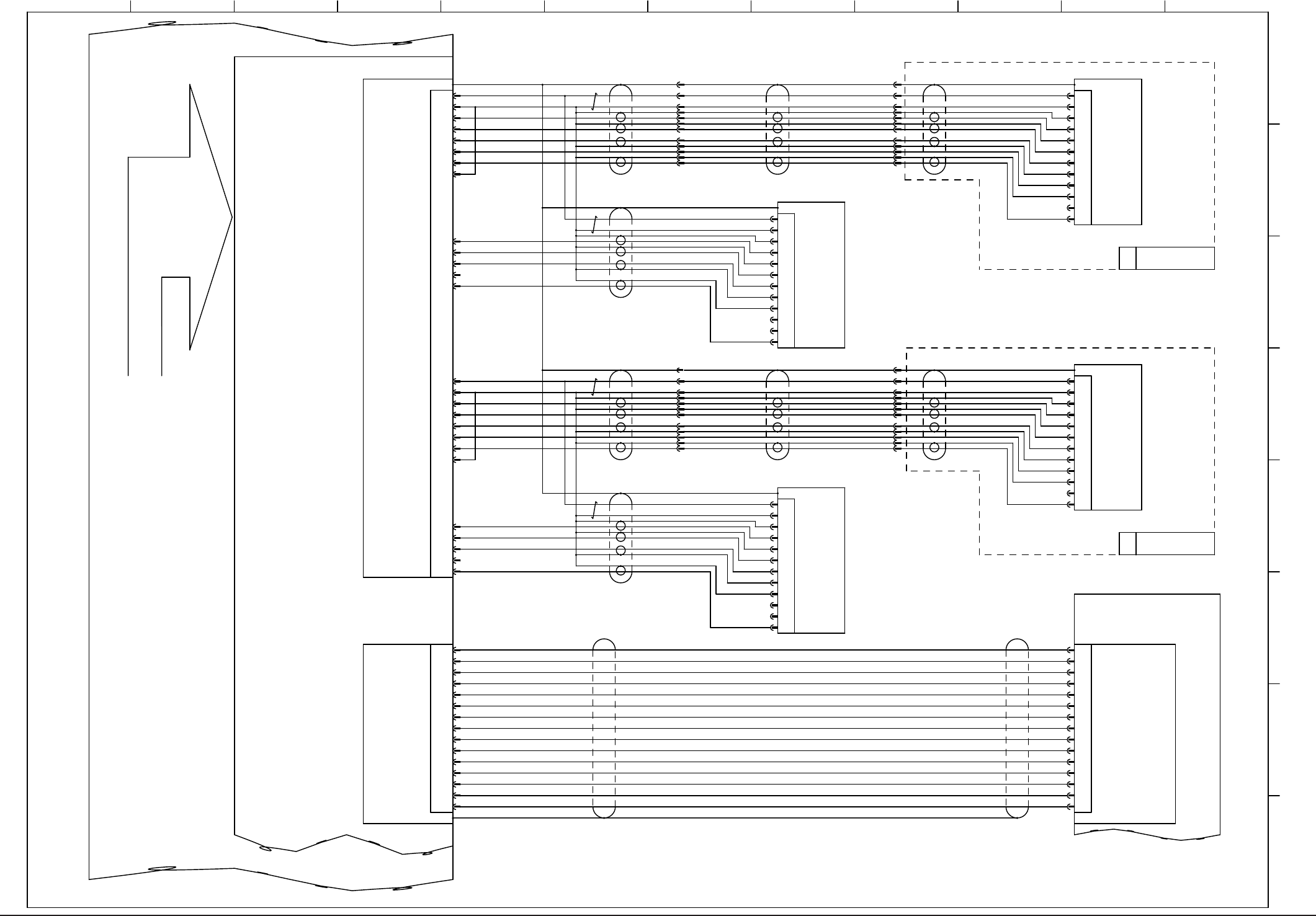
0712-001-(M867WR-A1002)
Recognition Unit Connection Diagram 3
2
3
GND15
CN3
1
5
6
9
10
8
7
14
13
12
11
4
+5V
GND
4
2
7
10
1
5
8
11
3
6
9
12 VD-
HD+
Video-
TRGER
GND
HD-
GND
-
VD+
+12V
Video+
P.S
4
2
7
10
1
5
8
11
3
6
9
12 VD-
HD+
Video-
TRGER
GND
HD-
GND
-
VD+
+12V
Video+
P.S
P.S
Video+
+12V
VD+
-
GND
HD-
GND
TRGER
Video-
HD+
VD-12
9
6
3
11
8
5
1
10
7
2
4
VIDEO-Cam3
CTRL2-Cam3
HDrive-Cam3
VDrive-Cam2
VIDEO-Cam1
VDrive-Cam4
HDrive-Cam4
CTRL1-Cam3
VDrive-Cam3
GND
CTRL1-Cam2
CTRL2-Cam2
CTRL1-Cam1
CTRL1-Cam4
CTRL2-Cam4
+12V
VIDEO-Cam4
CTRL2-Cam1 24
22
21
20
19
18
16
15
2
13
12
11
10
9
7
4
3
1
25
26VDrive-Cam1
HDrive-Cam1
4
2
7
10
1
5
8
11
3
6
9
12 VD-
HD+
Video-
TRGER
GND
HD-
GND
-
VD+
+12V
Video+
P.S
CAMERA
PIO
X9301
20
1
19
8
10
6
18
2
7
9
13
12
17
3
16GND
PIO_2
Strobe_0
PIO_1
PIO_3
Trig_2
Trig_0
PIO_0
PIO_11(Strobe1)
GND
Trig_3
Trig_1
Strobe_2
PIO_15(Strobe3)
+5V_PIO
X9303
-X3601
-X6101
-X6101
X9503
U95
+12V 23
GND 6
VIDEO-Cam2 5
HDrive-Cam2 17
:2
:12
:9
:6
:3
:11
:8
:5
:1
:7
:4
-X13601
:2
:12
:9
:6
:3
:11
:8
:5
:1
:7
:4
GND 8
GND 14
-X23601
U93
:2
:12
:9
:6
:3
:11
:8
:5
:1
:7
:4
-X3601
-X13601 -X23601
ROBOT CABLE
ROBOT CABLE
HM-G300(3)
U
HM-G300(4)
U
(Frame Grabber 2)
:2
:12
:9
:6
:3
:11
:8
:5
:1
:7
:4
bus
D-B61(3)
M-B36(3)
M-B36(4)
D-B61(4)
1
2 3 4 5 6 7 8 9 10 11 12
A
B
C
D
E
F
G
H
Connector Case Connector Case
Capture Trigger B1
Capture Trigger B2
Capture Trigger A1
Capture Trigger A2
Strobe Flashing Error Signal A
Strobe Flashing Error Signal B
Reserved B
Strobe Signal A
PEC Recognition Lighting ON Signal B
Strobe Signal B
PEC Recognition Lighting ON Signal A
Reserved A
Connector Case
Connector Case
Connector Case
Connector CaseConnector Case
Shell
Shell
Recognition BOX
Comp Recog Camera (3)
PEC Recognition
Camera (3)
PEC Recognition
Camera (4)
Comp Recog Camera (4)
Lighting Control Board
Recognition Board2
ShellShell
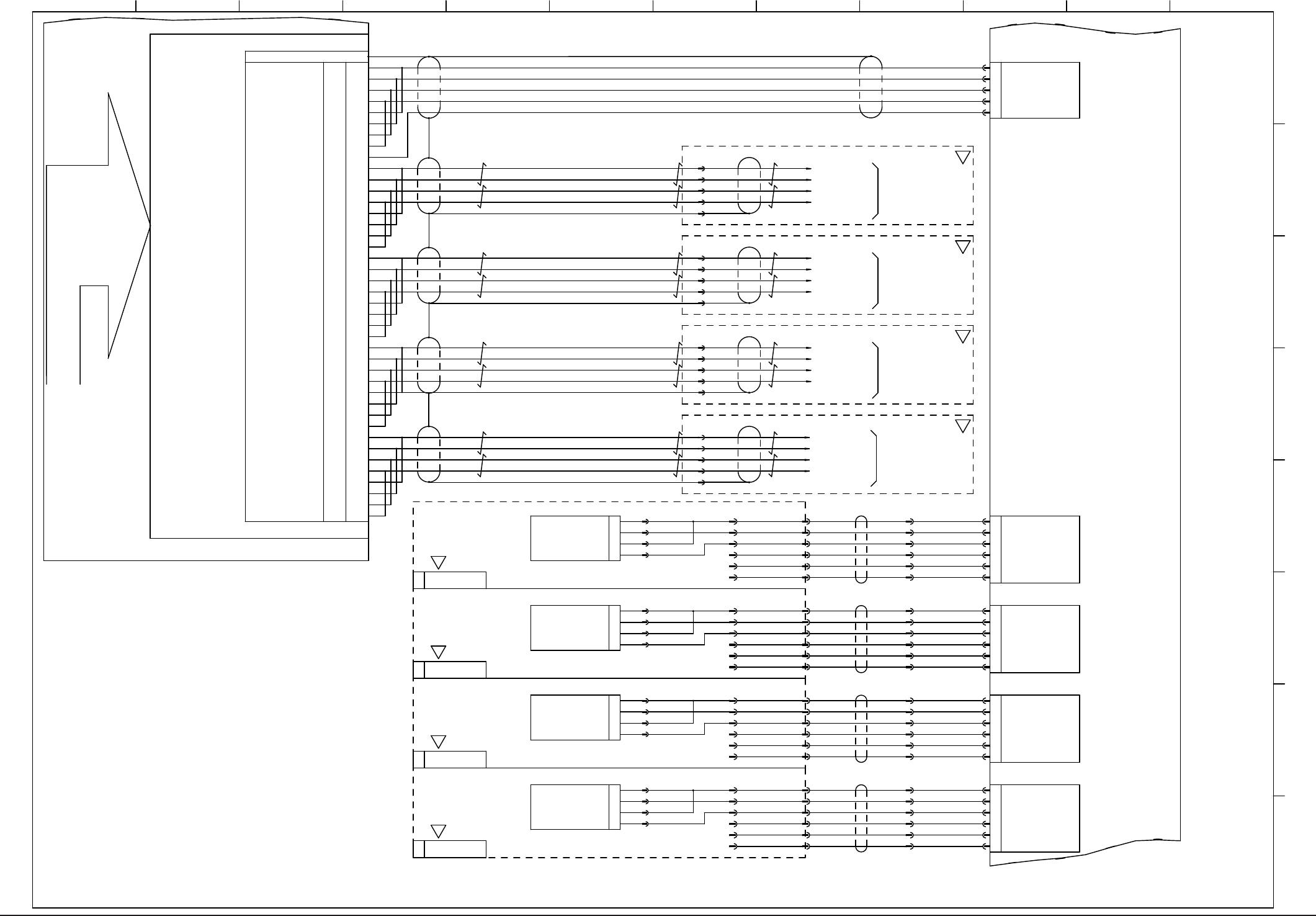
75
0712-001-(M867WR-A1003)
Recognition Unit Connection Diagram 4
TRG-B
TRG-A
GND
TRG-D
TRG-C
1
CN5
CN1
〈Robot Cable〉
PEC
Recognition Lighting (Coaxial)
1
+24V
+24V
PEC
Recognition Lighting (Ring)
PEC
Recognition Lighting (Coaxial)
PEC
Recognition Lighting (Ring)
PEC
Recognition Lighting (Coaxial)
PEC
Recognition Lighting (Ring)
PEC
Recognition Lighting (Coaxial)
PEC
Recognition Lighting (Ring)
OUT-A1
+24V
OUT-A4
+24V
OUT-A3
CN6
OUT-A2
U94
U95
-E39(1)
CH3 Actuation A Phase Input+
B44
B43
B42
B41
A43
A42
A41
CH7 Actuation B Phase Input-
CH7 Actuation A Phase Input+
CH7 Actuation B Phase Input+
CH3 Actuation B Phase Input-
CH7 Actuation A Phase Input-
CH3 Actuation B Phase Input+
CH3 Actuation A Phase Input-
8
7
6
5
56
55
54
53
A44
CH2 Actuation A Phase Input+
B36
B35
B34
B33
A35
A34
A33
CH6 Actuation B Phase Input-
CH6 Actuation A Phase Input+
CH6 Actuation B Phase Input+
CH2 Actuation B Phase Input-
CH6 Actuation A Phase Input-
CH2 Actuation B Phase Input+
CH2 Actuation A Phase Input-
16
15
14
13
64
63
62
61
A36
CH1 Actuation A Phase Input+
B28
B27
B26
B25
A27
A26
A25
CH5 Actuation B Phase Input-
CH5 Actuation A Phase Input+
CH5 Actuation B Phase Input+
CH1 Actuation B Phase Input-
CH5 Actuation A Phase Input-
CH1 Actuation B Phase Input+
CH1 Actuation A Phase Input-
24
23
22
21
72
71
70
69
A28
A20
CH7 Shingle Shot Output
CH6 Shingle Shot Output
CH5 Shingle Shot Output
CH4 Shingle Shot Output
Connector Case
77
78
79
80
29
30
31
32
41
91
90
93
92
42
43
44
45
CH1 Shingle Shot Output
CH0 Shingle Shot Output
CH0 Actuation A Phase Input-
CH0 Actuation A Phase Input+
CH0 Actuation B Phase Input+
GND
CH2 Shingle Shot Output
CH3 Shingle Shot Output
A04
A05
A06
A07
B05
B04
CH4 Actuation A Phase Input-
CH0 Actuation B Phase Input-
CH4 Actuation B Phase Input+
CH4 Actuation A Phase Input+
CH4 Actuation B Phase Input-
B07
B06
A08
A17
A18
A19
B17
B18
B19
B20
-X19506
:1
:2
:3
:4
:5
:6
-X12507
:8
:9
:10
:11
:12
:13
2
3
4
-E61
-E39
CN7
-E39(2)
CN8
-E39(3)
CN9
-E39(4)
[C-/03/4E]
[C-/04/4E]
[C-/05/4E]
[C-/06/4E]
HM-G300(1)
U
HM-G300(2)
U
HM-G300(3)
U
HM-G300(4)
U
2
3
4
5
1
2
3
4
5
6
OUT-A1
+24V
OUT-A4
+24V
OUT-A3
OUT-A2
1
2
3
4
5
6
OUT-A1
+24V
OUT-A4
+24V
OUT-A3
OUT-A2
1
2
3
4
5
6
OUT-A1
+24V
OUT-A4
+24V
OUT-A3
OUT-A2
1
2
3
4
5
6
:1
:2
:3
:4
:5
:6
〈Robot Cable〉
〈Robot Cable〉
1
+24V
+24V
-X19506
:1
:2
:3
:4
:5
:6
-X12507
:8
:9
:10
:11
:12
:13
2
3
4
-E61
-E39
:1
:2
:3
:4
:5
:6
〈Robot Cable〉
〈Robot Cable〉
1
+24V
+24V
-X19506
:1
:2
:3
:4
:5
:6
-X12507
:8
:9
:10
:11
:12
:13
2
3
4
-E61
-E39
:1
:2
:3
:4
:5
:6
〈Robot Cable〉
〈Robot Cable〉
1
+24V
+24V
-X19506
:1
:2
:3
:4
:5
:6
-X12507
:8
:9
:10
:11
:12
:13
2
3
4
-E61
-E39
:1
:2
:3
:4
:5
:6
〈Robot Cable〉
bus
Recognition
BOX
X9509
X9508
X9507
X9505
X9506
X9401
X19401
X29401
X39401
X49401
Shell
:1
:2
:5
:3
:1
:2
:5
:3
:1
:2
:5
:3
:3
:5
:2
:1
-X2103:6
To X Beam (1)-U24
PEC
Recognition
Lighting
Counter Board
Lighting Control Board
Shell
Shell
Shell
/Phase B
Phase B
/Phase A
Phase A
/Phase B
Phase B
/Phase A
Phase A
/Phase B
Phase B
/Phase A
Phase A
/Phase B
Phase B
/Phase A
Phase A
-X2103:16
-X2103:7
-X2103:17
BA(1)
BA(2)
-X2103:17
-X2103:7
-X2103:16
-X2103:6
BC(3)
-X2103:17
-X2103:7
-X2103:16
-X2103:6
BC(4)
-X2103:17
-X2103:7
-X2103:16
-X2103:6
PEC
Recognition
Lighting
PEC
Recognition
Lighting
PEC
Recognition
Lighting
To X Beam (2)-U24
To X Beam (3)-U24
To X Beam (4)-U24
1
2 3 4 5 6 7 8 9 10 11 12
A
B
C
D
E
F
G
H
S
S
S
S
S
S
S
S
76
CN1
-X0501
-X0502 -X0704 -X0705
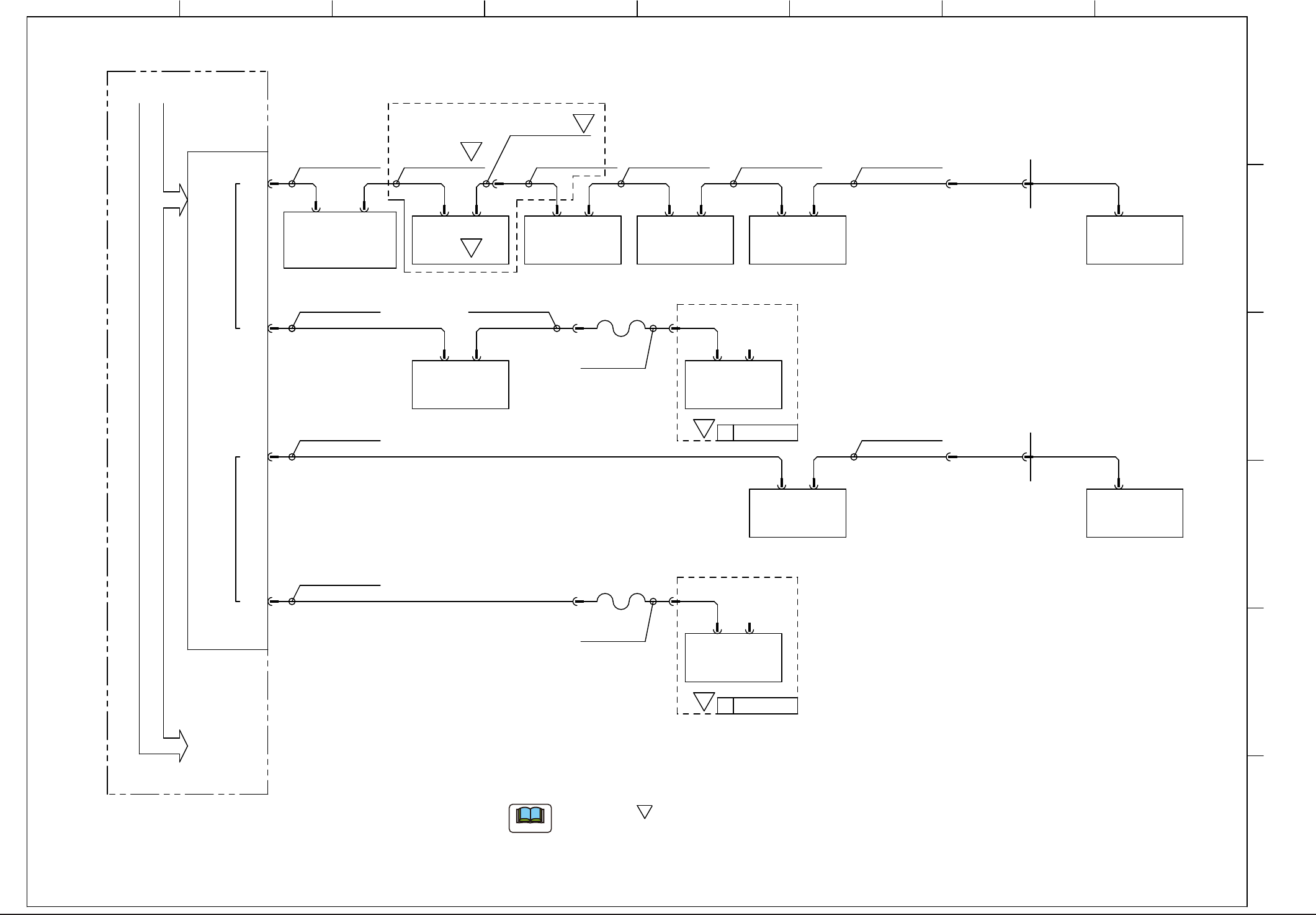
UB43
(Input / Output Machines)
-X0801 -X0802
UB32
(Transfer)
-X0902
UB32
(Cutter Positioning, Rear)
UB32
(Cutter Positioning, Front)
CN1
CN2
CH1
CH2
CN4
CN3
CN2
CN5CN4
CN2A/2BCN1A/1B CN2A/2BCN1A/1B
CN2A/2BCN1A/1B
-X20201
SCR
D-sub_9P
SCR SCR
SCR
RJ45
RJ45
RJ45
-U07 -U08 -U09
-X10306
-X0901
-X20201
D-sub
9P
RJ45
D-sub_9P
-U69
RJ45
CN80
UB34(Feeder Base)
-X6980
-X30
-X1300B
-X1300B
-X30
-X6980
UB34(Feeder Base)
CN80
RJ45
-U69
-U85
HLSB-PCI
-U09
-X0902-X0901
-X0101 -X0102
UB32
(Operation Panel, Rear)
CN2A/2BCN1A/1B
SCR
-U01
UB13(Head I/O)
-X1701
-U17
-U05
-X1603 -X1604
UA54(ILB)
CN4CN3
-U16
D-sub
9P
(-X11604)
(-X0502)
-X1702
CN2A/2BCN1A/1B
U
UB13(Head I/O)
-X1701
-U17
-X1702
CN2A/2BCN1A/1B
U
HM-G300(1)
HM-G300(2)
-X10306
UB64
1 2 3 4 5 6 7 8
A
B
C
D
E
F
BL)S951 DX)S752
630 154 0696
DX)S753
630 157 7364
BL)S953
630 158 6649
C-)S252
C-)S252
630 158 6649
<ROBOT CABLE>
<ROBOT CABLE>
(0.5m)(0.7m)(2.3m)(1.5m)
(3.0m)
DX)S754
630 157 7371
(0.6m)
DX)S755
630 154 0726
(3.5m)
630 150 5466
630 150 5473
630 150 5848
BA)S951
BL)S954 (3.5m)
630 154 1945
BL)S952 (3.5m)
630 1505800
BA)S983
630 157 7357
(1.0m)
630 158 9282
BA)SA151
630 158 9312
BA)SA152 (0.3m)
(0.3m)
S
Note b
Note b
S
S
S
S
The Mark " " shows the connection document for your reference when
the multi-functional heads are mounted on the Block 1 or Block 2.
(a)
The cables are shown on the unit name of HM-G300 (multi-functional head)
side on the diagram.
(b)
S
Note
0712-001-(M845JA-A1037)
CPU2-L Cable Connection (HLS)