LA 404-2 Pattern Controller Manual.pdf - 第20页
LA 404-2 Patt ern Control Sys tem 14 P/N 7 1 19995A 2006 Nordson Corporation LA 4 04- 2 Is sued 12/06 Performance Item Specification Maximum operational line speed 600 m/min, 1 p/mm encoder gearing Maximum pulse fre- que…
LA 404-2 Pattern Control System
13
P/N 7119995A
2006 Nordson Corporation
LA 404-2
Issued 12/06
Specifications
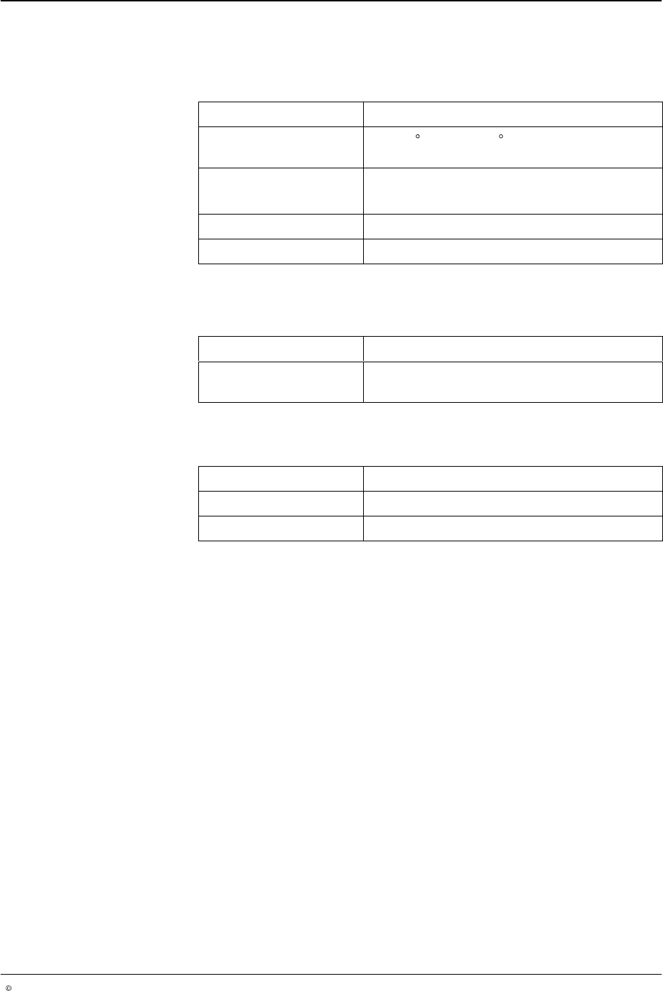
Operating Conditions
Item Specification
Ambient temperature
range
0 − 40 C (32 − 104 F)
Enclosure rating IP40
Humidity 5 % − 95 % (non−condensing)
Altitude -20 − 5000 feet above sea level
Physical Data
Item Specification
Dimensions (WxDxH) 310 mm x 270 mm x 205 mm (12.2 in. x 10.6
in. X 8.0 in.)
Power supply
Item Specification
Input voltage 85 − 240 V
AC
, 50/60 Hz
Replacement fuse 5 x 20 mm, 250 V
AC
, 3.15 A
LA 404-2 Pattern Control System
14
P/N 7119995A
2006 Nordson Corporation
LA 404-2
Issued 12/06
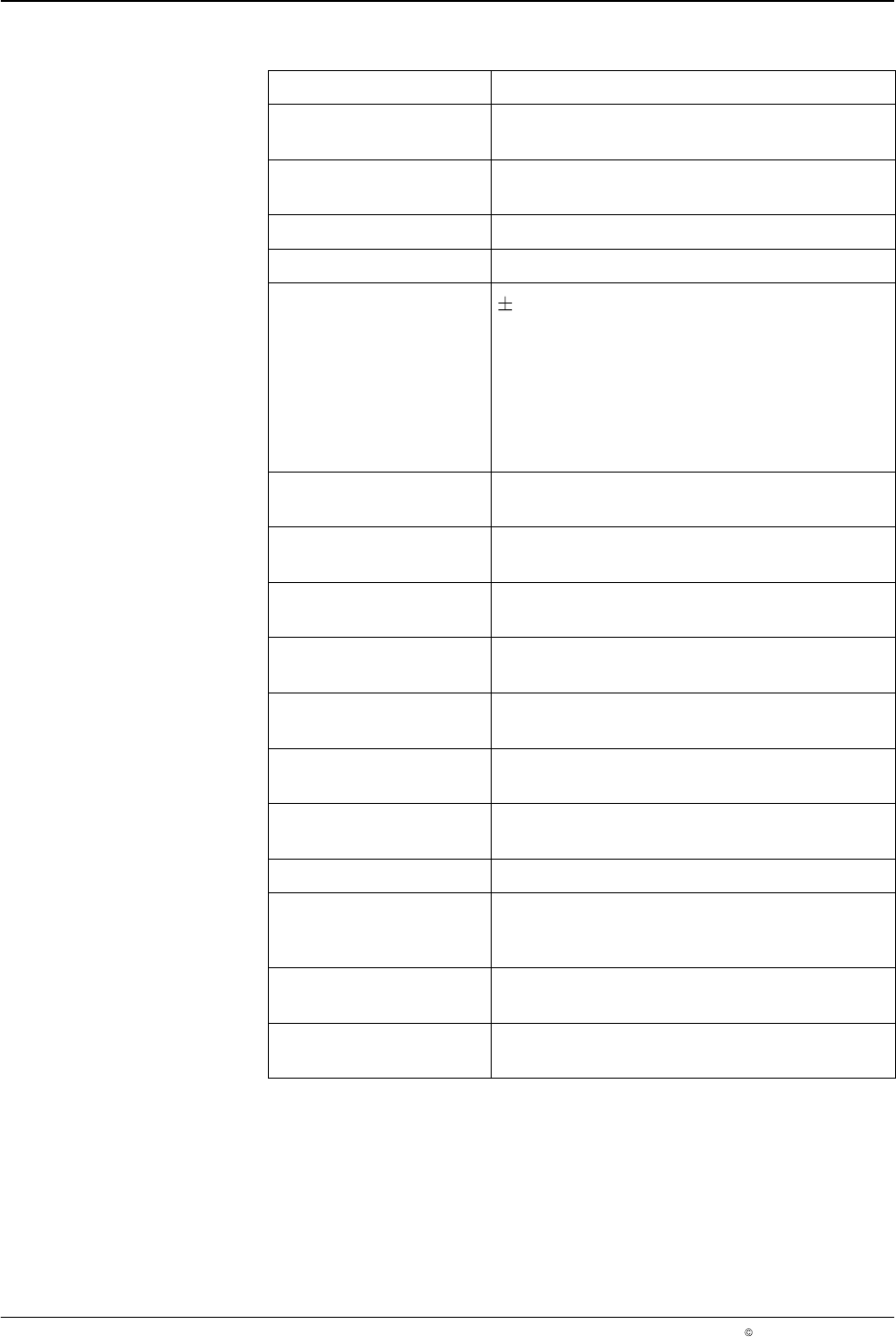
Performance
Item Specification
Maximum operational
line speed
600 m/min, 1 p/mm encoder gearing
Maximum pulse fre-
quency
100 kHz
Encoder resolution 0.1 p/mm − 20 p/mm
Bead resolution 1.0 mm
Adhesive placement ac-
curacy
1.0 mm under the following conditions:
a. Encoder resolution at least 1 p/mm
b. Acceleration levels +2.0 m/s
2
and -2.0
m/s
2
(0 − maximum line speed)
c. Gun compensation (on/off) 5.0 ms or less
d. All triggers activated simultaneously
Gun compensation
range
0 - 500 mm in steps of 0.1 mm at a pre-
scribed speed
Trigger setup time Processes all trigger inputs and generates the
initial gun output within 1 ms
Line speed sensor input
(encoder or MSD)
One encoder input that accepts single and
quadrature type encoders
Number of channel and
gun output
Four programmable channel (or gun) outputs
Maximum number of
beads per channel
Four beads per programmed channel
Maximum pattern seg-
ment length
32768 encoder pulses
Minimum bead delay
(gap)
0 mm
Maximum bead duration Equal to the maximum pattern segment length
Minimum programmable
gun-to-trigger offset
(GTO)
2 mm
Maximum gun-to-trigger
offset (GTO)
Equal to maximum pattern segment length
minus the first bead offset
Digital circuitry I/O
insulation
All remote inputs and outputs are electrically
insulated from the internal digital circuits
LA 404-2 Pattern Control System
15
P/N 7119995A
2006 Nordson Corporation
LA 404-2
Issued 12/06
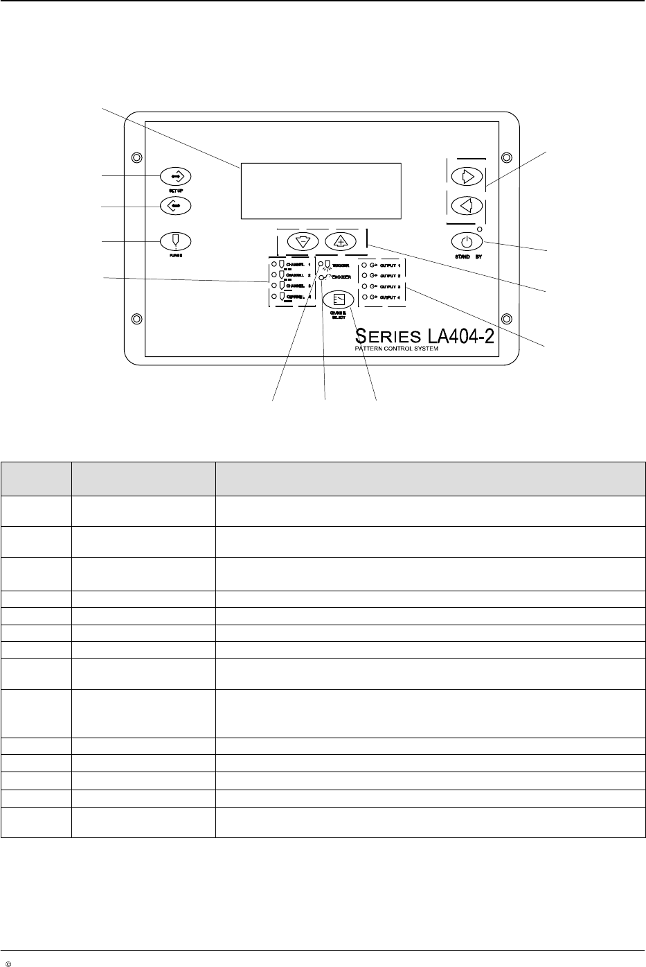
Front Panel
The front panel is used for entering and displaying the user inputs and
transmitting the inputs to the pattern generation engine.
1
2
3
4
56
8
9
10
11
12
7
O652
Fig. 2 Location of Front Panel Controls and Indicators
Item Controls and
Indicators
Description
1 Right arrow or Left
arrow
Selects the item being programmed by moving up or down.
2 STAND BY Enables and disables the gun output. When active (amber LED)disables all
channels. When inactive (green LED) all channels are permitted to run.
3
Up (increase) arrow or
Down (decrease) arrow
Increases or decreases the value of the selected parameter.
4 OUTPUT 1- 4 LEDs Illuminates when the selected gun output is activated.
5 CHANNEL SELECT Selects which channel is being programmed, observed or adjusted.
6 ENCODER LED Illuminates with each pulse from the encoder.
7 TRIGGER LED Illuminates when the selected trigger is On.
8 CHANNEL 1 - 4 LEDs Illuminates to indicate that the selected channel is being programmed,
observed or adjusted. The LEDs blink to indicate a warning condition.
9 PURGE Activates all outputs for active channel only.
NOTE: In flush mode it acts as an On/Off button. In purge mode it is a
momentary contact that is On when pressed and Off when released.
10 SETUP backward Scrolls backward through the setup screens.
11 SETUP forward Scrolls forward through the setup screens.
12
Setup menu screen Alphanumeric, 4 x 20 backlight LCD
- Cursor or asterisk (*) Appears beside a parameter to indicate that it is ready for setup.
- Hash (#) Appears at the top left of a page when a parameter has been changed. The
hash character disappears 10 seconds after the saving process.