LA 404-2 Pattern Controller Manual.pdf - 第71页
War nings A − 1 P/N 7 1 1 9995A 2006 Nordson Corporation LA 4 04- 2 Is sued 12/06 Appendix A W arnings These are messages that are displaye d on the menu screen to indicate a warning condition. Engine W arnings The follo…

LA 404-2 Pattern Control System
64
P/N 7119995A
2006 Nordson Corporation
LA 404-2
Issued 12/06
Refer to Trigger.
The glue gun stops when the machine stops, and resumes to
complete the current gluing cycle when the machine restarts.
The duration of high voltage or current spike at the initiation of an
electric gun firing.
Refer to Dot Bead Type.
Refer to Dot Pitch.
Refer to Dot Time.
Refer to Modulated Bead Type.
This feature allows the reduction of adhesive usage by entering
the percentage of glue savings. The pattern control
automatically determines the correct length and spacing of the
sub-beads in the bead pattern. Refer also to Sub-Bead.
A bead that results when the pattern control divides a continuous
bead into smaller spaced beads. Sub-beads are used in the
generation of custom bead types (stitched beads, dot beads, and
modulated beads).
The product edge that causes the trigger to stop sensing the
product as the product passes by the trigger. Refer also to
Leading Edge.
A device that receives an analog current signal from the pattern
control and uses it to regulate air pressure. A transducer is used
only in systems equipped for run-up control. Refer also to
Run-Up Control.
A photosensor that detects products as they travel along the
production line. The pattern control can be equipped with one or
two triggers, depending upon the requirements of the DC
application.
Distance that a photosensor passes from the trigger edge to the
other edge of the product. The photosensor is disabled for the
distance entered for the lockout value, thereby preventing
unwanted triggering caused by any holes or contrasting colors on
the product.
A user-determined setting (T-MEM) that allows the user to either
apply or not apply adhesive to products between the trigger and
the guns when line speed recovers after falling below the
minimum-speed setting. If a minimum speed is set, the pattern
control will stop generating patterns whenever the line speed falls
below this speed.
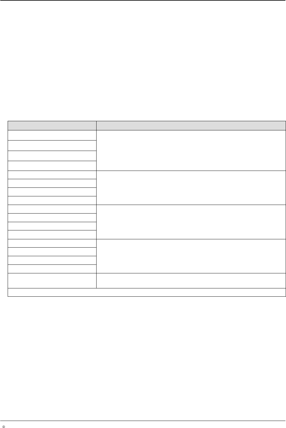
Sensor
Set Mode
Spike Time
Spot Glue/
Spot Mode/Spot Pattern
Spot Pitch
Spot Time
Spotting
Stitched Bead Type
Sub-Bead
Trailing Edge
Transducer
Trigger
Trigger Mask
Trigger Memory Mode
Warnings
A−1
P/N 7119995A
2006 Nordson Corporation
LA 404-2
Issued 12/06
Appendix
A
Warnings
These are messages that are displayed on the menu screen to indicate a
warning condition.
Engine Warnings
The following engine warnings appear on the menu screen.
Screen Message Explanation and Action
Out1 queue overflow
This warning appears if there are more than 4 products between the gun and
its associated trigger. There should never be more than 4 products between
the trigger and the gun. If this occurs, the pattern controller will not generate
pattern on the additional products between the gun and trigger.
To correct this, increase the distance between products or decrease the
distance between the trigger and the gun.
Out2 queue overflow
Out3 queue overflow
Out4 queue overflow
Output 1 forced This is a pattern generation error that is caused by a gun not turning on or off
(or both) soon enough. The bead start point or end point has already passed
when the signal is sent to the gun actuator.
To correct this, decrease the line speed or add more space between the
trigger and the gun, or between the beads.
Output 2 forced
Output 3 forced
Output 4 forced
TRG1 too short This warning appears when the pattern for a channel exceeds the product
length as seen by the assigned trigger.
Verify proper product placement. This is an indication that the pattern would
not fit onto the product as measured by the trigger. It could indicate a jam or
skewed product.
TRG2 too short
TRG3 too short
TRG4 too short
T1 max dist exceeded
This warning indicates that the measured product length is longer than the
user entered maximum product length. Also refer to Jamming.
To correct this, check for a possible jam on the production line.
T2 max dist exceeded
T3 max dist exceeded
T4 max dist exceeded
Trigger queue full The warning indicates that more than 2 products are located between the
trigger and gun.
Continued...
Warnings
A−2
P/N 7119995A
2006 Nordson Corporation
LA 404-2
Issued 12/06
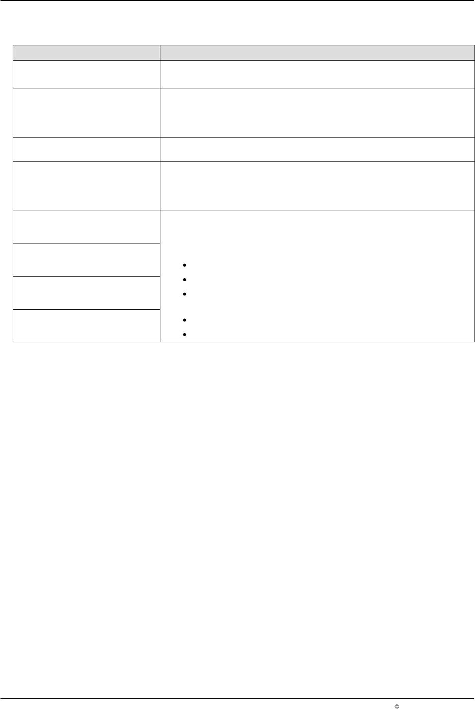
Engine Warnings
(Cont..)
Screen Message Explanation and Action
Communications Error This warning appears when there is an unspecified problem with the LA404.
If the problem persists, contact your Nordson representative for assistance.
Lost encoder signal
This warning appears when the encoder signal is not detected (encoder did
not move while the system was in the Run mode and at least 2 trigger signals
were received).
To correct this, confirm that the encoder is working correctly.
Encoder missing
This warning appears when RUN-mode is activated by pressing the STAND
BY-button but there is no encoder connected.
Max bead exceeded
This warning appears if the distance limit from one edge of the bead to the
other edge of the bead has been exceeded.
To correct this, make the beads smaller, make the gaps between each bead
smaller, change the encoder gearing, or decrease the GTO.
Ch1 short circuit
Gun Driver Overload. This fault appears when the loads on the gun driver is
drawing more than 100 Watts. This may be due to too many guns
connected, improper settings, or defective loads.
To correct this:
Check spike time and hold voltage settings for the type of gun used.
Check resistance of guns being driven.
Electric guns should be greater than 8 ohms and pneumatic valves
should be greater than 45 ohms.
Check the cable for a short.
The gun driver may be defective.
Ch2 short circuit
Ch3 short circuit
Ch4 short circuit
Engine Warning Codes
The warning codes appear as numeric codes on the menu screen. To
correct the condition, default the pattern controller to the factory settings. If
the problem persists, contact your Nordson representative for assistance.