LA 404-2 Pattern Controller Manual.pdf - 第26页
LA 404-2 Patt ern Control Sys tem 20 P/N 7 1 19995A 2006 Nordson Corporation LA 4 04- 2 Is sued 12/06 Installation This section provide s pattern controller positioning information and basic startup instructions. Pattern…

7
2
3
1
4
5
8
6
O660
C
B
L
G
H
M
J
K
A
F
E
D
O656
LA 404-2 Pattern Control System
19
P/N 7119995A
2006 Nordson Corporation
LA 404-2
Issued 12/06
Remote Input
Female connector. The drawing shows the front view (pin side).
Pin Signal
1 24 V
DC
, max. 0.2 A
2 Not Connected
3 Not Connected
4 Not Connected
5 Not Connected
6 Not Connected
7 Remote enable
8 24 V
DC
common
Remote Output
Male connector. The drawing shows the rear view (solder side).
Pin Signal
A Remote alarm output, normally closed contact
B Remote alarm output, normally open contact
C Remote alarm output, ground contact
D RUN-mode active, normally closed contact
E RUN-mode active, normally open contact
F RUN-mode active, ground contact
G Channel 1 active (24 V
DC
, 0.1 A)
H Channel 2 active (24 V
DC
, 0.1 A)
J Channel 3 active (24 V
DC
, 0.1 A)
K Channel 4 active (24 V
DC
, 0.1 A)
L Ground of active channel at output
M Sends signals on a drop below the minimum speed
and during purging (24 V
DC
, 0.1 A)
LA 404-2 Pattern Control System
20
P/N 7119995A
2006 Nordson Corporation
LA 404-2
Issued 12/06
Installation
This section provides pattern controller positioning information and basic
startup instructions.
Pattern Controller Ship-With Kit
The following contents are included in the pattern controller ship-with kit:
Kit Contents Quantity
Fuses 2
Mounting bracket 2
Power cable, 230 V
AC
1
Power cable, 110 V
AC
1
Manual 1
Unpacking and Positioning the Pattern Controller
1. Exercise care to prevent equipment damage during unpacking.
2. Inspect the equipment for any damage that may have occurred during
shipping. Report any damage to the Nordson representative.
3. Bolt each mounting bracket (included in the pattern controller ship-with
kit) on either side of the pattern controller firmly.
4. Position the pattern controller close to the production line.
WARNING: Equipment must be properly grounded and fused according to
its rated current consumption (see ID plate). Failure to follow the safety
procedures can result in serious injury.
5. Connect the pattern controller power cord to a properly grounded wall
outlet.
NOTE: This pattern controller can be connected by means of power
cables for 110 V
AC
or 230 V
AC
. If a different power cable needs to be
used, the users must provide it themselves.
LA 404-2 Pattern Control System
21
P/N 7119995A
2006 Nordson Corporation
LA 404-2
Issued 12/06
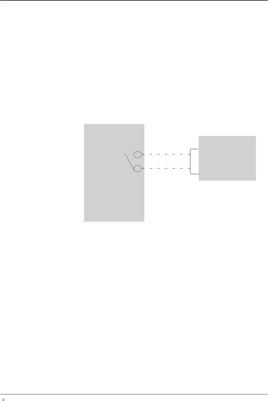
Remote Input Plug
The remote input plug provided in the ship-with kit connects to the Remote
Input connector. It is typically used to prevent the pattern controller from
dispensing adhesive until a melter or parent machine is ready, as shown in
Figure 4.
To enable the pattern controller to begin dispensing adhesive:
Connect the 24 V
DC
(Remote Input plug, pin 1) to the remote enable
input (Remote Input plug, pin 7) using an electrically isolated contact.
Refer to the Remote Input pin drawing under I/O Connector Pin Layout.
To bypass (or to set to INACTIVE) the remote enable function, refer to
System Settings 1.
O661
Melter
LA 404-2 Pattern Controller
1
7
Remote input
connectors
Ready contact
Fig. 4 Connecting the pattern controller to the Melter for Pattern Generation