LA 404-2 Pattern Controller Manual.pdf - 第29页
LA 404-2 Pattern Co ntrol System 23 P/N 71 19995A 2006 Nordson Corporation LA 404-2 Issued 12/ 06 Quick Programming Gui de This Quick Programm ing Guide explains the organization of the various me nus in Administrato r-,…

LA 404-2 Pattern Control System
22
P/N 7119995A
2006 Nordson Corporation
LA 404-2
Issued 12/06
Remote Output Plug
The remote output plug provided in the ship-with kit connects to the Remote
Output connector.
Pin Description
A, B and C These pins can be used as alarm outputs, e.g. for
connection to a lamp column or buzzer.
D, E and F If the STAND BY button is actuated in RUN-mode,
the contact is closed. This contact can, for
example, be connected to the parent machine to
trigger enabling of the production line.
The Remote Input initially sends a signal to the
melter to enable the production line. If the LA 404-2
pattern controller is in STAND-BY-mode, however,
the production line must not start up. Start up of the
production line may only occur when the LA 404-2
pattern controller is in RUN-mode.
G, H, J, K and L These pins are activated according to the program
selected. The wire of the output currently in use is
set to 24 V
DC
. This signaling is independent of
STAND-BY- or RUN-mode. These signals are
normally used to activate the heaters in the case of
applications using several melters.
M Signals to the melters indicating adhesive is now
being applied.
LA 404-2 Pattern Control System
23
P/N 7119995A
2006 Nordson Corporation
LA 404-2
Issued 12/06
Quick Programming Guide
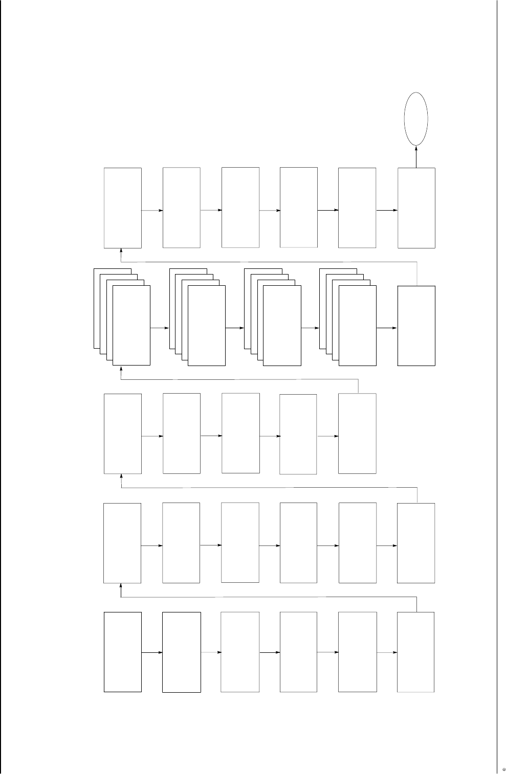
This Quick Programming Guide explains the organization of the various menus in Administrator-, Setup- and Operator modes.
Dly1: 251 Dur1: 25
Dly2: 277 Dur2: 25
Dly3: 303 Dur3: 25
Dly4: 329 Dur4: 25
Bead Type Channel 4
Normal Continuous
Modulation Seam
Autospot Random
Chan 4 Compensation
Pull−in 00.0 mm
Drop-out 00.0 mm
Set speed 60 m/min
Chan 3 Compensation
Pull-in 00.0 mm
Drop-out 00.0 mm
Set speed 60 m/min
Chan 2 Compensation
Pull-in 00.0 mm
Drop-out 00.0 mm
Set speed 60 m/min
Chan 4 Driver Setup
Peak voltage 32 V
Spike time 1.8 ms
Hold voltage 5 V
Chan 3 Driver Setup
Peak voltage 32 V
Spike time 1.8 ms
Hold voltage 5 V
Chan 2 Driver Setup
Peak voltage 32 V
Spike time 1.8 ms
Hold voltage 5 V
Administrator Mode:
Program 1..100
Speed 60 m/min
Work rate 0/hr
Total 0
V3.26
Start
Administrator
Channel Assignment
Channel 1 Active
Trigger 1
Trigger Assignment
Channel 2 Active
Trigger 1
Trigger Assignment
Channel 3 Active
Trigger 1
Trigger Assignment
Channel 4 Active
Trigger 2
Setup Trigger 1
Trigger Light On
JAM detection Off
JAMtolerance 5 mm
Setup Trigger 2
Trigger Light On
JAM detection Off
JAMtolerance 5 mm
Setup Trigger 3
Trigger Light On
JAM detection Off
JAMtolerance 5 mm
Setup Trigger 4
Trigger Light On
JAM detection Off
JAMtolerance 5 mm
Trigger 1 Settings
Prod.length 100 mm
GTO 50 mm
Masking 5 mm
Trigger 2 Settings
Prod.length 100 mm
GTO 50 mm
Masking 5 mm
Trigger 3 Settings
Prod. length 100 mm
GTO 50 mm
Masking 5 mm
Trigger 4 Settings
Prod.length 100 mm
GTO 50 mm
Masking 5 mm
Pressure 1 Settings
Speed1 0 P1 0%
Speed2 100 P2 80%
Min 0% Max 100%
Pressure 2 Settings
Speed1 0 P1 0%
Speed2 100 P2 80%
Min 0% Max 100%
Purge Pressure
Run−up 1 10%
Run−up 2 10%
Purge Mode Purge
Chan 1 Driver Setup
Peak voltage 32 V
Spike time 1.8 ms
Hold voltage 5 V
Chan 1 Compensation
Pull-in 00.0 mm
Drop-out 00.0 mm
Set Speed 60 m/min
Bead Type Channel 3
Normal Continuous
Modulation Seam
Autospot Random
Bead Type Channel 2
Normal Continuous
Modulation Seam
Autospot Random
Bead Type Channel 1
Type #type
Dly1: 251 Dur1: 25
Dly3: 277 Dur3: 25
Dly3: 303 Dur3: 25
Dly4: 329 Dur4: 25
Dly1: 251 Dur1: 25
Dly2: 277 Dur2: 25
Dly3: 303 Dur3: 25
Dly4: 329 Dur4: 25
Dly1: 251 Dur1: 25
Dly2: 277 Dur2: 25
Dly3: 303 Dur3: 25
Dly4: 329 Dur4: 25
Program 01
Save as 01 No
Recall 01 No
Copy CH# to CH# No
Warnings
Encoder Scaling
Encoder Single
Custom 1.000 ppmm
Direction Forward
Low Speed Setting
Start 10 m/min
Stop 5 m/min
System Settings 1
Language English
Autostart Off
Rem enable Active
System Settings 2
Trigger memory Off
Clipping Off
Tip seal Settings
Mode Automatic
Dwell time 3.0 s
Start
Max dot 100 m/min
#type: Normal, Continuous, Autospot, Dot, Random, Random Stitch
LA 404-2 Pattern Control System
24
P/N 7119995A
2006 Nordson Corporation
LA 404-2
Issued 12/06
Dly1: 251 Dur1: 25
Dly2: 277 Dur2: 25
Dly3: 303 Dur3: 25
Dly4: 329 Dur4: 25
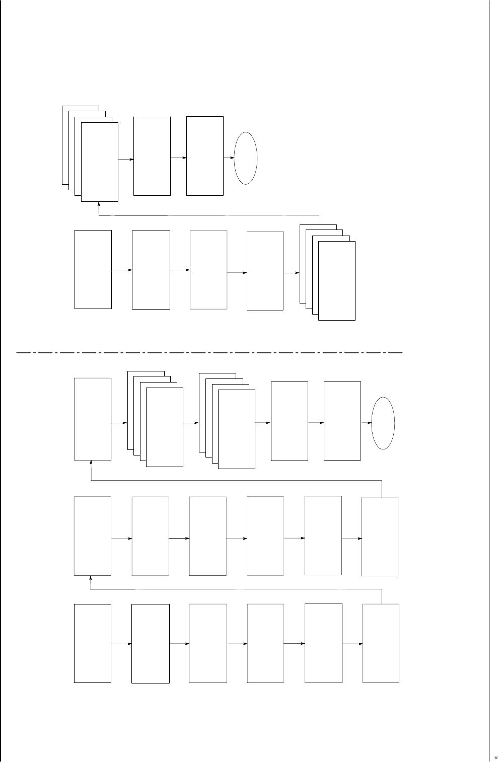
Setup mode:
Program 1..100
Speed 60 m/min
Work rate 0/hr
Total 0
V3.26
Setup
Trigger Assignment
Channel 1 Active
Trigger 1
Trigger Assignment
Channel 2 Active
Trigger 1
Trigger Assignment
Channel 3 Active
Trigger 1
Trigger Assignment
Channel 4 Active
Trigger 2
Trigger 1 Settings
Prod.length 100 mm
GTO 50 mm
Masking 5 mm
Trigger 2 Settings
Prod.length 100 mm
GTO 50 mm
Masking 5 mm
Trigger 3 Settings
Prod.length 100 mm
GTO 50 mm
Masking 5 mm
Trigger 4 Settings
Prod.length 100 mm
GTO 50 mm
Masking 5 mm
Pressure 1 Settings
Speed1 0 P1 0%
Speed2 100 P2 80%
Min 0% Max 100%
Pressure 2 Settings
Speed1 0 P1 0%
Speed2 100 P2 80%
Min 0% Max 100%
Purge Pressure
Run−up 1 10%
Run−up 2 10%
Purge Mode Purge
Dly1: 251 Dur1: 25
Dly2: 277 Dur2: 25
Dly3: 303 Dur3: 25
Dly4: 329 Dur4: 25
Dly1: 251 Dur1: 25
Dly2: 277 Dur2: 25
Dly3: 303 Dur3: 25
Dly4: 329 Dur4: 25
Dly1: 251 Dur1: 25
Dly2: 277 Dur2: 25
Dly3: 303 Dur3: 25
Dly4: 329 Dur4: 25
Program 01
Save as 01 No
Recall 01 No
Copy CH# to CH# No
Warnings
Start
Start
Dly1: 251 Dur1: 25
Dly2: 277 Dur2: 25
Dly3: 303 Dur3: 25
Dly4: 329 Dur4: 25
Operator mode:
Program 1..100
Speed 60 m/min
Work rate 0/hr
Total 0
V3.26
Operator
Pressure 1 Settings
Speed1 0 P1 0%
Speed2 100 P2 80%
Min 0% Max 100%
Pressure 2 Settings
Speed1 0 P1 0%
Speed2 100 P2 80%
Min 0% Max 100%
Dly1: 251 Dur1: 25
Dly2: 277 Dur2: 25
Dly3: 303 Dur3: 25
Dly4: 329 Dur4: 25
Dly1: 251 Dur1: 25
Dly2: 277 Dur2: 25
Dly3: 303 Dur3: 25
Dly4: 329 Dur4: 25
Dly1: 251 Dur1: 25
Dly2: 277 Dur2: 25
Dly3: 303 Dur3: 25
Dly4: 329 Dur4: 25
Program 01
Save as 01 No
Recall 01 No
Copy CH# to CH# No
Warnings
Start
Start
Bead Type Channel 4
Normal Continuous
Modulation Seam
Autospot Random
Bead Type Channel 3
Normal Continuous
Modulation Seam
Autospot Random
Bead Type Channel 2
Normal Continuous
Modulation Seam
Autospot Random
Bead Type Channel 1
Type #type
Bead Type Channel 4
Normal Continuous
Modulation Seam
Autospot Random
Bead Type Channel 3
Normal Continuous
Modulation Seam
Autospot Random
Bead Type Channel 2
Normal Continuous
Modulation Seam
Autospot Random
Bead Type Channel 1
Type #type