LA 404-2 Pattern Controller Manual.pdf - 第24页
1 2 3 4 5 O657 1 2 3 O658 1 5 4 3 2 6 O659 1 2 3 4 5 O657 LA 404-2 Patt ern Control Sys tem 18 P/N 7 1 19995A 2006 Nordson Corporation LA 4 04- 2 Is sued 12/06 Tip Seal Input Female connector . The drawing shows the fron…
1
2
3
3
O654
1
2
3
4
O655
C
B
L
G
H
M
J
K
A
F
E
D
O656
LA 404-2 Pattern Control System
17
P/N 7119995A
2006 Nordson Corporation
LA 404-2
Issued 12/06
I/O Connector Pin Layout
The I/O connector pin layouts are shown below to make the appropriate
cable connections.
Channel 1 - 4
Female connector. The drawing shows the front view (pin side).
Pin Signal
1 Gun +
2 not used
3 Gun −
4 Chassis
Run−up 1 and 2
Female connector. The drawing shows the front view (pin side).
Pin Signal
1 24 V
DC
common
2 0 - 20 mA output
3 0 - 10 Volt output
4 24 V
DC
, max. 0.35 A
Encoder Input
Female connector. The drawing shows the front view (pin side).
Pin Signal
A 24 V
DC
(quadrature differential)
B Signal A (quadrature differential)
C Signal A not (quadrature differential)
D Signal B (quadrature differential)
E Signal B not (quadrature differential)
F 24 V
DC
common (quadrature differential)
G 24 V
DC
(single pulse)
H Pulse train input (single pulse)
J 24 V
DC
common (single pulse)
K Quadrature differential encoder type (connect to
common for quadrature differential encoders)
L Pulse train encoder type (connect to encoders for
pulse)
M 24 V
DC
common

1
2
3
4
5
O657
1
2
3
O658
1 5
4
3
2
6
O659
1
2
3
4
5
O657
LA 404-2 Pattern Control System
18
P/N 7119995A
2006 Nordson Corporation
LA 404-2
Issued 12/06
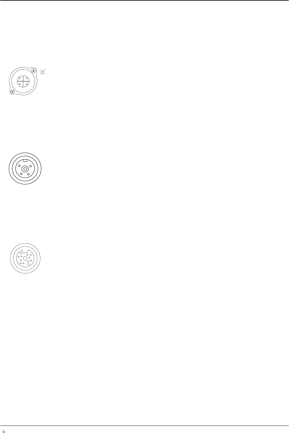
Tip Seal Input
Female connector. The drawing shows the front view (pin side).
Pin Signal
1 N/A
2 Trigger (NPN or PNP)
3 24 V
DC
, max. 0.1 A
4 24 V
DC
common
5 N/A
Tip Seal Output
Female connector. The drawing shows the front view (pin side).
Pin Signal
1 Output, 24 V
DC,
max. 0.7 A
2 24 V
DC
common
3 Chassis
Remote Purge Input
Female connector. The drawing shows the front view (pin side).
Pin Signal
1 Purge channel 1
2 Purge channel 2
3 Purge channel 3
4 Purge channel 4
5 24 V
DC
common
6 24 V
DC
common
Trigger Input
Female connector. The drawing shows the front view (pin side).
Pin Signal
1 N/A
2 Trigger (NPN or PNP)
3 24 V
DC
, max. 0.1 A
4 24 V
DC
common
5 N/A

7
2
3
1
4
5
8
6
O660
C
B
L
G
H
M
J
K
A
F
E
D
O656
LA 404-2 Pattern Control System
19
P/N 7119995A
2006 Nordson Corporation
LA 404-2
Issued 12/06
Remote Input
Female connector. The drawing shows the front view (pin side).
Pin Signal
1 24 V
DC
, max. 0.2 A
2 Not Connected
3 Not Connected
4 Not Connected
5 Not Connected
6 Not Connected
7 Remote enable
8 24 V
DC
common
Remote Output
Male connector. The drawing shows the rear view (solder side).
Pin Signal
A Remote alarm output, normally closed contact
B Remote alarm output, normally open contact
C Remote alarm output, ground contact
D RUN-mode active, normally closed contact
E RUN-mode active, normally open contact
F RUN-mode active, ground contact
G Channel 1 active (24 V
DC
, 0.1 A)
H Channel 2 active (24 V
DC
, 0.1 A)
J Channel 3 active (24 V
DC
, 0.1 A)
K Channel 4 active (24 V
DC
, 0.1 A)
L Ground of active channel at output
M Sends signals on a drop below the minimum speed
and during purging (24 V
DC
, 0.1 A)