LA 404-2 Pattern Controller Manual.pdf - 第56页
LA 404-2 Patt ern Control Sys tem 50 P/N 7 1 19995A 2006 Nordson Corporation LA 4 04- 2 Is sued 12/06 Encoder Scaling This menu is used to display the encoder type and co nfigure the encoder scaling. The pattern controll…

LA 404-2 Pattern Control System
49
P/N 7119995A
2006 Nordson Corporation
LA 404-2
Issued 12/06
Warnings
The pattern controller monitors warning conditions like:
Trigger 1 - 4 too short (clipping), T1- 4 max distance exceeded (jamming),
Ch1 - 4 short circuit, etc.
NOTE: Warnings appear in the display. They remain visible until they are
acknowledged by pressing any button.
The pins A, B and C at the remote output (refer to Page 22) are wired as an
alarm output. The alarm output can be used for a machine stop signal or to
trigger a remote device.
When a fault occurs, there are two cases in which the alarm output is
activated. In all other cases, only a warning appears in the display.
1. Short circuit of the gun output
2. The jam detector signals a fault
Warnings
O682
Fault Condition
A fault condition occurs typically when there is a hardware or software
defect. When a fault condition occurs, the user will need to take immediate
action.
Warning Condition
A warning condition alerts the user that there may be an error with the
setup of the pattern controller. When a warning condition occurs, immediate
action may not be required.
LA 404-2 Pattern Control System
50
P/N 7119995A
2006 Nordson Corporation
LA 404-2
Issued 12/06
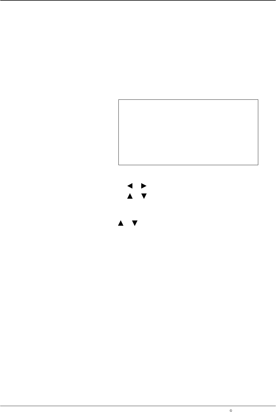
Encoder Scaling
This menu is used to display the encoder type and configure the encoder
scaling. The pattern controller automatically detects the type of encoder
installed. If no encoder is detected, the Not connected message appears in
the display.
The encoder scaling ratio is determined by entering the number of pulses
per millimeter that the encoder outputs when installed. If a quadrature
encoder is used, the direction of rotation travel maybe reversed.
Encoder Scaling
Encoder Single
Custom 1,000 ppmm
Direction Forward
O683
1. To set the encoder scaling
a. Press the or button for the cursor to appear beside Custom.
b. Press the or button to set the encoder gearing ratio from
0.1 - 20,000 ppmm (pulses per millimeter).
2. To set the encoder direction
Press the or button to set Direction to Forward or Backward.
NOTE: The direction parameter is used only if a quadrature encoder is
detected.
LA 404-2 Pattern Control System
51
P/N 7119995A
2006 Nordson Corporation
LA 404-2
Issued 12/06
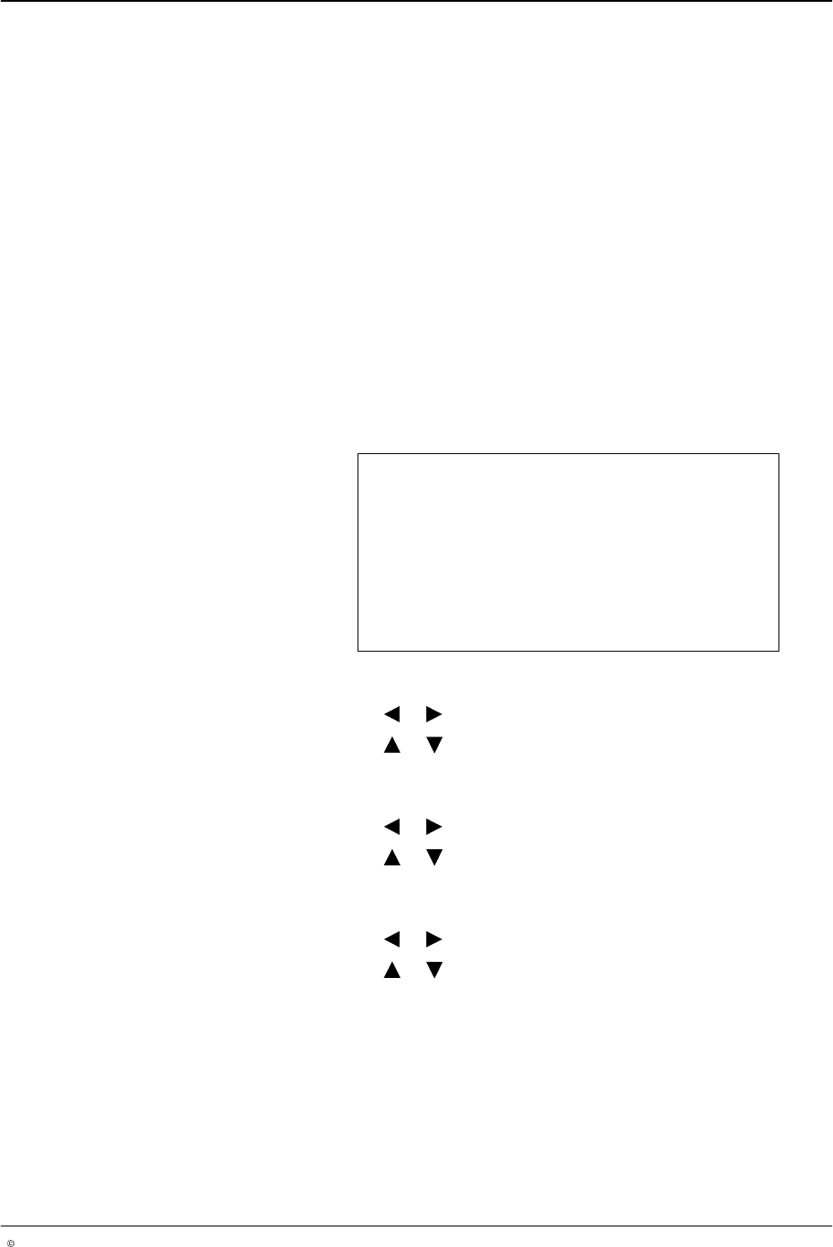
Low Speed Settings
This setup menu is used to configure the minimum operational line speed
above which the guns will begin dispensing, and below which the guns will
stop dispensing adhesive. Setting this feature prevents a puddle of
adhesive from forming when the line stops.
CAUTION: When using the Random Dot and Dot Bead modes, it is
recommended to set a maximum speed (Max Dot) which must not be
exceeded due to the risk of the guns overheating. The standard value is
100 m/min, but it can be adjusted.
NOTE: If the production machine speed is above the maximum dot speed
(Max Dot), a normal bead is applied (also refer to Page 15).
NOTE: Low speed settings override the line speed settings for continuous
bead patterns.
Low Speed Setting
Start 0 m/min
Stop 1 m/min
Max Dot 100 m/min
O684
1. To set start speed
a. Press the or button for the cursor to appear beside Start.
b. Press the or button to set the desired value from
0 - 600 m/min.
2. To set stop speed
a. Press the or button for the cursor to appear beside Stop.
b. Press the or button to set the desired value from
0 - 600 m/min.
3. To set max dot speed
a. Press the or button for the cursor to appear beside Max Dot.
b. Press the or button to set the desired value from
0 - 600 m/min.
NOTE: The Max Dot speed is relevant for the following bead types:
Autospot, Dot and Random Dot.