LA 404-2 Pattern Controller Manual.pdf - 第42页
LA 404-2 Patt ern Control Sys tem 36 P/N 7 1 19995A 2006 Nordson Corporation LA 4 04- 2 Is sued 12/06 Channel Comp ensation Entering channel compensation settings ensures accurate placement of the beads in applications w…
LA 404-2 Pattern Control System
35
P/N 7119995A
2006 Nordson Corporation
LA 404-2
Issued 12/06
Channel Driver Setup
Each of the four channels has a programmable voltage-controlled gun
driver. The user may program the spike time duration and hold voltage for
each channel.
NOTE: The spike voltage is displayed and cannot be changed.
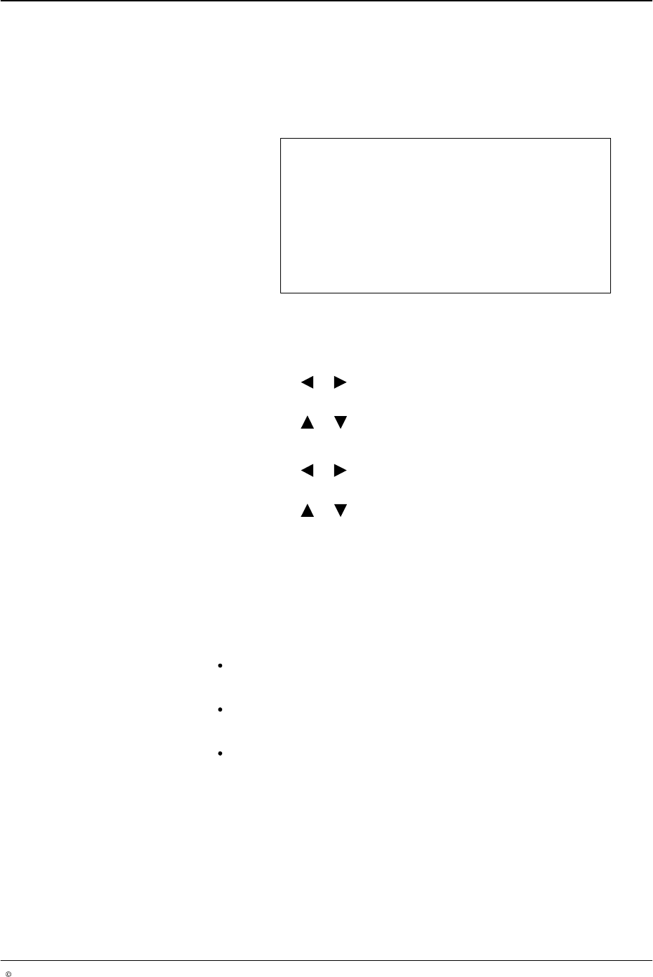
Chan 1 Driver Setup
Spike voltage 32 V
Spike time 1.8 ms
Hold voltage 5 V
O670
1. To select channels 1 - 4, press the CHANNEL SELECT button on the
front panel of the pattern controller.
2. To set Spike time
a. Press the or button for the cursor to appear beside the numeric
value.
b. Press the or button to set the desired value from 0.0 - 5.0 ms.
3. To set hold voltage
a. Press the or button for the cursor to appear beside the numeric
value.
b. Press the or button to set to 5 V, 10 V, or 24 V.
NOTE: On selecting a hold voltage of 5 V, the period of the overvoltage
is 0.1 - 5.0 ms. On selecting a hold voltage of 10 V, the period of the
overvoltage is 0.1 - 15 ms. On selecting a hold voltage of 24 V, the
period of the overvoltage is 0.1 - 15 ms.
Guns Supported By Pattern Controller Driver Boards
Electric guns:
LA 820, recommended settings:
Spike time: 1.8 ms/Hold voltage: 5 V
LA 844, recommended settings:
Spike time: 2 ms/Hold voltage: 5 V
LA 822, recommended settings:
Spike time: 2.5 ms/Hold voltage: 10 V
The pattern controller supports 24 V
DC
pneumatic guns, recommended
settings: Spike time: 0 ms/Hold voltage: 24 V
LA 404-2 Pattern Control System
36
P/N 7119995A
2006 Nordson Corporation
LA 404-2
Issued 12/06
Channel Compensation
Entering channel compensation settings ensures accurate placement of the
beads in applications where the line speed varies. Manual entry of the time
required for each gun to open, and the time required for each gun to close
provides channel compensation. Different values of compensation for each
channel can be entered.
The compensation is entered in millimeters (mm).
The pattern controller provides a process with which compensation values
can be established and entered quickly. Set the Pull−in and Drop−out
compensation to zero, produce a Normal bead test pattern at production
speed. Enter the run speed under Set speed and measure the difference
between the actual bead placement and the programmed bead start. Enter
this value as the setting for Pull−in and measure the difference between the
actual bead end and the programmed bead end. Enter the measured value
for the Drop−out setting.
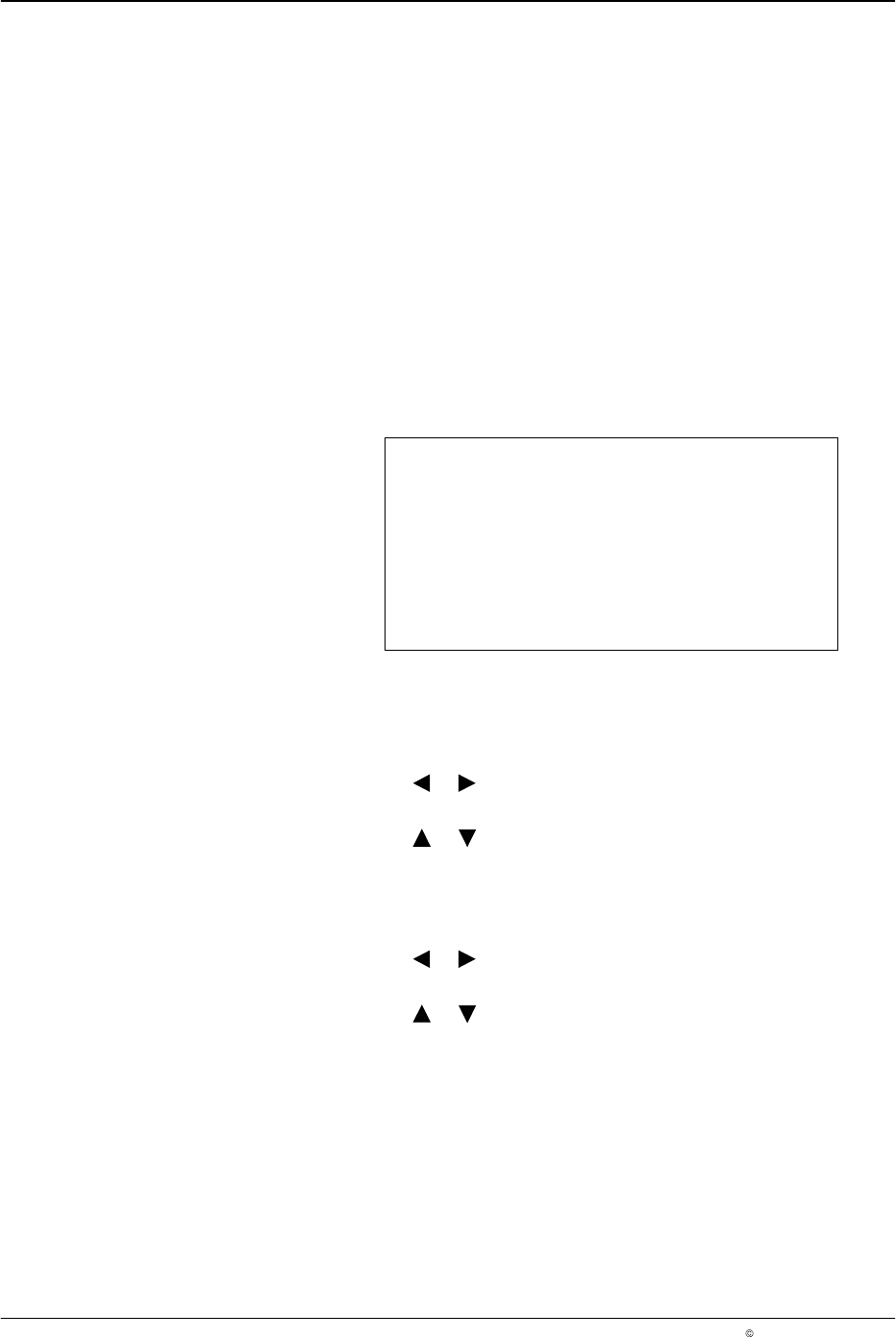
Chan 1 Compensation
Pull-in 00.0 mm
Drop-out 00.0 mm
Set Speed 60 m/min
O671
To select Chan (channel) 1 - 4, press the CHANNEL SELECT button on the
front panel of the pattern controller.
4. To set Pull−in
a. Press the or button for the cursor to appear beside the numeric
value.
b. Press the or button to set the desired Pull-in value from
00.0 − 500.0 mm.
NOTE: Pull−in is the amount of time prior to start of a bead.
5. To set Drop−out :
a. Press the or button for the cursor to appear beside the numeric
value.
b. Press the or button to set the desired Drop−out value from
00.0 - 500.0 mm.
NOTE: Drop−out is the amount of time prior to the finish of a bead.
LA 404-2 Pattern Control System
37
P/N 7119995A
2006 Nordson Corporation
LA 404-2
Issued 12/06
6. To set speed
a. Press the or button for the cursor to appear beside the numeric
value.
b. Press the or button to set the desired value from
1 - 600 m/min.
7. Repeat steps 2 − 3 to set channel 2 − 4.
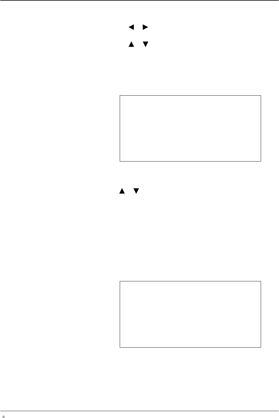
Bead Type (Channel 1 - 4)
This setting allows the user to select one of the six different bead types.
Bead Type Channel 1
Type Normal
O672
To select channels 1 - 4, press the CHANNEL SELECT button on the front panel of
the pattern controller.
8. Press the or button to select the bead type required Normal,
Continuous, Autospot, Dot, Random, Random Dot.
9. After selecting the bead type, press the top SETUP button to program
the selected bead. The following section discusses programming each
bead type.
10. Repeat steps 2 − 4 to set the bead type for Channel 2 − 4.
Normal Beads
When the line velocity is above the start speed (refer to Low Speed
Settings), a normal or a solid bead is generated. This is the default bead
type for each channel.
Dly1: 251 Dur1: 25
Dly2: 277 Dur2: 25
Dly3: 303 Dur3: 25
Dly4: 329 Dur4: 25
O673