LA 404-2 Pattern Controller Manual.pdf - 第35页
LA 404-2 Pattern Control System 29 P/N 7 1 1 9995A 2006 Nordson Corporation LA 4 04- 2 Is sued 12/06 Trigger Assignment In this menu, each o f the four chan nels can be activated and assigned one of the four trigger inpu…

LA 404-2 Pattern Control System
28
P/N 7119995A
2006 Nordson Corporation
LA 404-2
Issued 12/06
Production Data
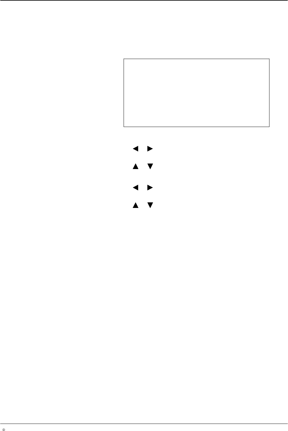
This menu offers the following parameters:
The program number is displayed. The program number is changed
after loading a different program.
Speed indicates the line speed measured by the encoder in meters
per minute. The speed is purely an indicator and cannot be altered.
Work rate is the production rate determined by Trigger 1.
Total is the number of products currently counted by Trigger 1.
Products below the low speed of the production line are not counted.
To reset Total, press the button on the front panel of the pattern
controller.
Program 1..100
Speed 60 m/min
Work rate 0/hr
Total 0
O665
LA 404-2 Pattern Control System
29
P/N 7119995A
2006 Nordson Corporation
LA 404-2
Issued 12/06
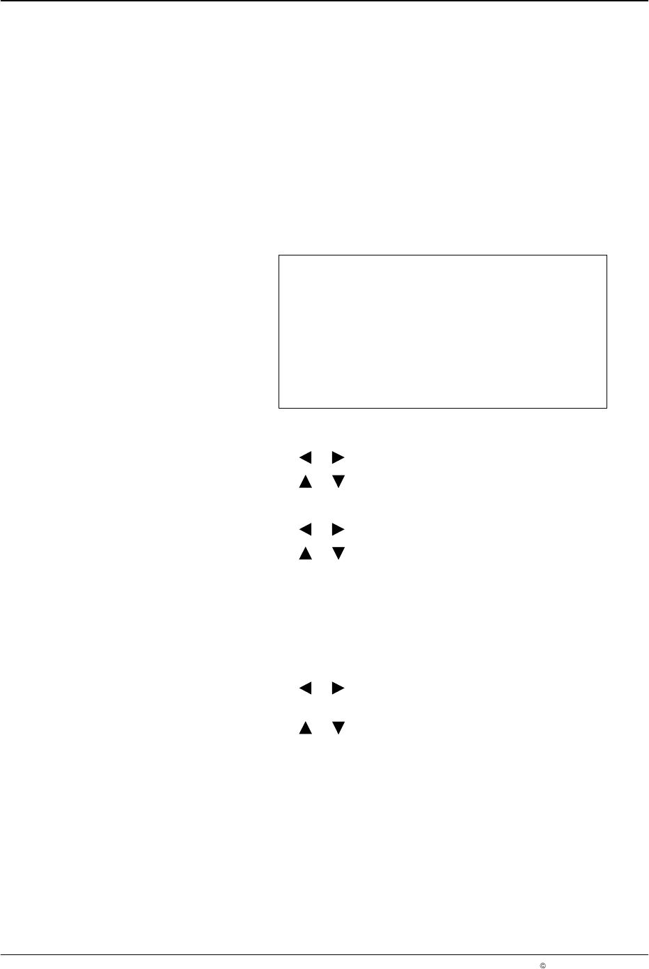
Trigger Assignment
In this menu, each of the four channels can be activated and assigned one
of the four trigger inputs.
Trigger Assignment
Channel 1 Active
Trigger 1
O666
1. To set Channel 1 to Active or Inactive
a. Press the or button for the cursor to appear beside Active or
Inactive.
b. Press the or button to select Active or Inactive.
2. To assign triggers 1 − 4 to a channel:
a. Press the or button for the cursor to appear beside the numeric
value.
b. Press the or button to select from trigger number’s 1 − 4.
NOTE: The assigned trigger number will be displayed in the Trigger
Settings menu.
3. Repeat steps 2 − 3 to set Channel number’s 2 − 4.
LA 404-2 Pattern Control System
30
P/N 7119995A
2006 Nordson Corporation
LA 404-2
Issued 12/06
Trigger (1 - 4) Configuration
After activating trigger’s 1 - 4 in the Trigger Assignment menu, this menu
serves to activate/deactivate the trigger and to define whether the product
or background should reflect. If the product is reflective, select the Light On
setting. Correspondingly, in the case of non−reflecting products, select the
Dark On setting.
If the jam detector is activated, a warning and signal are issued when the
photosensor is active for a period longer than the user-defined product
length plus the jam tolerance. In this case, the jam tolerance must be set for
each trigger.
Trigger 1 Config
Trigger Light On
JAM detection Off
JAMtolerance 5 mm
O667
1. Setting the Trigger Behavior
a. Press the or button for the cursor to appear beside Light On.
b. Press the or button to select Light On or Dark On.
2. To set JAM detection
a. Press the or button for the cursor to appear beside Off or On.
b. Press the or button to On or Off. If set to On, go to step 3 to
set the jam tolerance.
NOTE: The jam tolerance can only be set in Administrator mode. The jam
tolerance is only necessary when jam detection is activated. In addition, the
production length must be entered in Trigger # settings in the Setup menu
(refer to Page 31).
3. To set JAMtolerance
a. Press the or button for the cursor to appear beside the numeric
value.
b. Press the or button to select value from 0 - 9999 mm.