LA 404-2 Pattern Controller Manual.pdf - 第22页
LA 404-2 Patt ern Control Sys tem 16 P/N 7 1 19995A 2006 Nordson Corporation LA 4 04- 2 Is sued 12/06 Rear P anel The rear panel contains several input/output (I/O) connectors that connec t the pattern con troller to oth…
LA 404-2 Pattern Control System
15
P/N 7119995A
2006 Nordson Corporation
LA 404-2
Issued 12/06
Front Panel
The front panel is used for entering and displaying the user inputs and
transmitting the inputs to the pattern generation engine.
1
2
3
4
56
8
9
10
11
12
7
O652
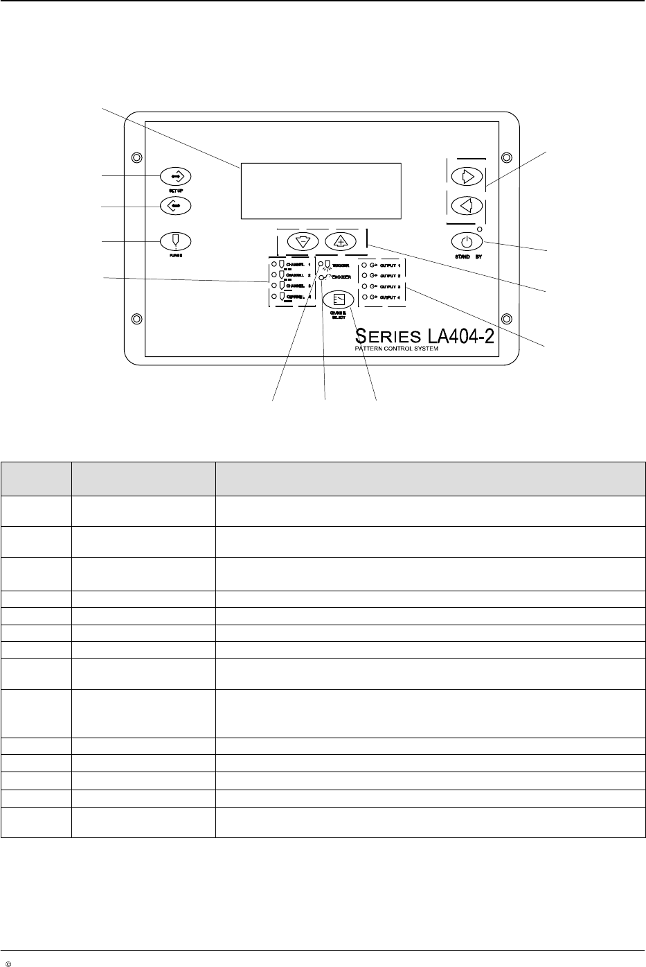
Fig. 2 Location of Front Panel Controls and Indicators
Item Controls and
Indicators
Description
1 Right arrow or Left
arrow
Selects the item being programmed by moving up or down.
2 STAND BY Enables and disables the gun output. When active (amber LED)disables all
channels. When inactive (green LED) all channels are permitted to run.
3
Up (increase) arrow or
Down (decrease) arrow
Increases or decreases the value of the selected parameter.
4 OUTPUT 1- 4 LEDs Illuminates when the selected gun output is activated.
5 CHANNEL SELECT Selects which channel is being programmed, observed or adjusted.
6 ENCODER LED Illuminates with each pulse from the encoder.
7 TRIGGER LED Illuminates when the selected trigger is On.
8 CHANNEL 1 - 4 LEDs Illuminates to indicate that the selected channel is being programmed,
observed or adjusted. The LEDs blink to indicate a warning condition.
9 PURGE Activates all outputs for active channel only.
NOTE: In flush mode it acts as an On/Off button. In purge mode it is a
momentary contact that is On when pressed and Off when released.
10 SETUP backward Scrolls backward through the setup screens.
11 SETUP forward Scrolls forward through the setup screens.
12
Setup menu screen Alphanumeric, 4 x 20 backlight LCD
- Cursor or asterisk (*) Appears beside a parameter to indicate that it is ready for setup.
- Hash (#) Appears at the top left of a page when a parameter has been changed. The
hash character disappears 10 seconds after the saving process.
LA 404-2 Pattern Control System
16
P/N 7119995A
2006 Nordson Corporation
LA 404-2
Issued 12/06
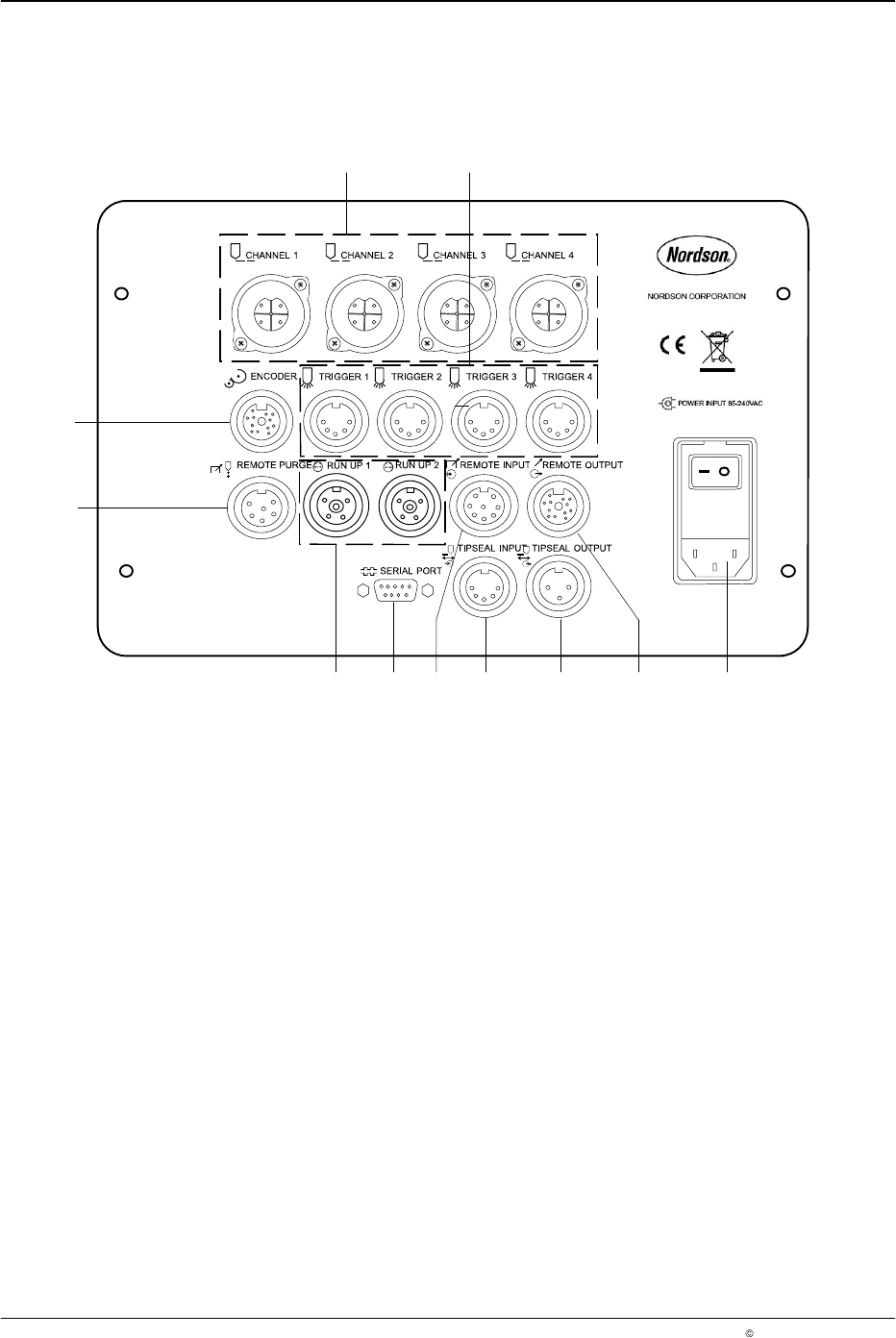
Rear Panel
The rear panel contains several input/output (I/O) connectors that connect
the pattern controller to other
devices.
O65
3
2
1
11
10
69 8 35 47
Fig. 3 Connection sockets on the rear panel
1. CHANNEL 1 - 4 (outputs)
2. TRIGGER 1 - 4
3. POWER INPUT
85 - 240 V
AC
4. REMOTE OUTPUT
5. TIPSEAL OUTPUT
6. TIPSEAL INPUT
7. REMOTE INPUT
8. SERIAL PORT
Used for software updates
9. RUN UP 1 - 2
10. REMOTE PURGE
11. ENCODER
1
2
3
3
O654
1
2
3
4
O655
C
B
L
G
H
M
J
K
A
F
E
D
O656
LA 404-2 Pattern Control System
17
P/N 7119995A
2006 Nordson Corporation
LA 404-2
Issued 12/06
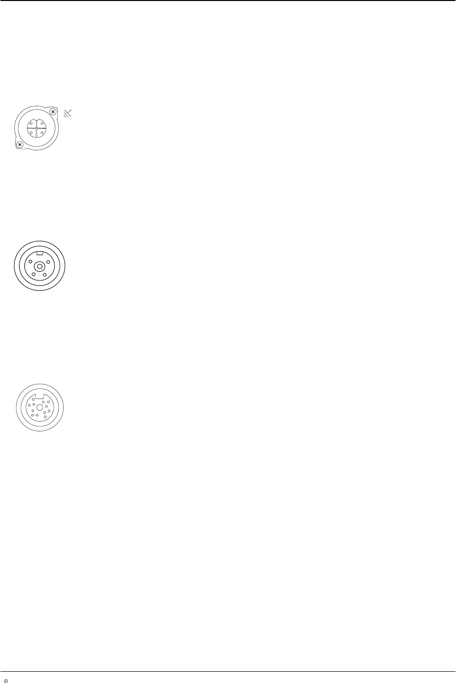
I/O Connector Pin Layout
The I/O connector pin layouts are shown below to make the appropriate
cable connections.
Channel 1 - 4
Female connector. The drawing shows the front view (pin side).
Pin Signal
1 Gun +
2 not used
3 Gun −
4 Chassis
Run−up 1 and 2
Female connector. The drawing shows the front view (pin side).
Pin Signal
1 24 V
DC
common
2 0 - 20 mA output
3 0 - 10 Volt output
4 24 V
DC
, max. 0.35 A
Encoder Input
Female connector. The drawing shows the front view (pin side).
Pin Signal
A 24 V
DC
(quadrature differential)
B Signal A (quadrature differential)
C Signal A not (quadrature differential)
D Signal B (quadrature differential)
E Signal B not (quadrature differential)
F 24 V
DC
common (quadrature differential)
G 24 V
DC
(single pulse)
H Pulse train input (single pulse)
J 24 V
DC
common (single pulse)
K Quadrature differential encoder type (connect to
common for quadrature differential encoders)
L Pulse train encoder type (connect to encoders for
pulse)
M 24 V
DC
common