LA 404-2 Pattern Controller Manual.pdf - 第60页
LA 404-2 Patt ern Control Sys tem 54 P/N 7 1 19995A 2006 Nordson Corporation LA 4 04- 2 Is sued 12/06 System Settings 2 This setup menu is u sed to configure the trigger memory and trigger clipping functions. The trigger…

LA 404-2 Pattern Control System
53
P/N 7119995A
2006 Nordson Corporation
LA 404-2
Issued 12/06
3. To set remote enable
a. Press the or button for the cursor to appear beside Active.
b. Press the or button to select Active or Inactive.
When set to Active, ensure the following:
Connect the plug provided in the ship-with kit to the Remote
Input connector, refer to Remote Enable Plug explained earlier
in the manual.
Connect the 24 V
DC-
plug (Remote input, pin 1) on the input
Remote enable (Remote input, pin 7) with an electrically isolated
contact; refer to plug Remote input.
To bypass this function, set the Remote enable parameter to
Inactive.
LA 404-2 Pattern Control System
54
P/N 7119995A
2006 Nordson Corporation
LA 404-2
Issued 12/06
System Settings 2
This setup menu is used to configure the trigger memory and trigger
clipping functions.
The trigger memory function allows the user to either apply or not apply
adhesive to products between the trigger and the guns when line speed
recovers after falling below the stop speed setting. When set to off, the
pattern is terminated, and when set to on the pattern resumes when the line
speed is above the start speed setting.
Clipping inhibits the pattern output if the product length measured by the
photosensor is shorter than the programmed pattern for a specific channel.
This feature is typically used to prevent glue from being applied to skewed
products. When pattern clipping is detected, a warning is displayed in the
Warnings screen and the warning relay is activated.
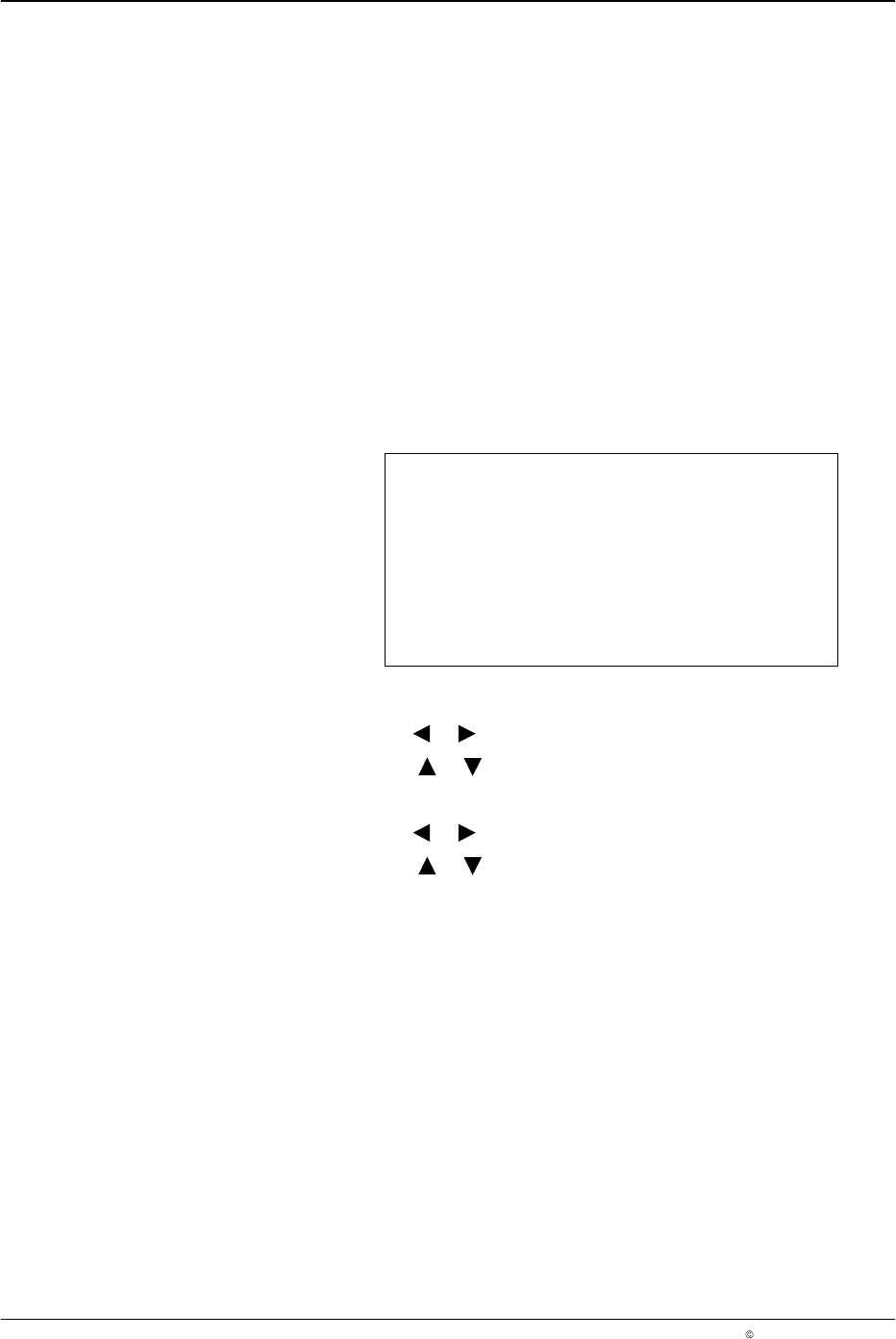
System Setting 2
Trigger Memory Off
Clipping Off
O686
1. To set the trigger memory
a. Press the or button for the cursor to appear beside On or Off.
b. Press the or button and select On or Off.
2. To set clipping
a. Press the or button for the cursor to appear beside On or Off.
b. Press the or button and select On or Off.
LA 404-2 Pattern Control System
55
P/N 7119995A
2006 Nordson Corporation
LA 404-2
Issued 12/06
Tip Sealer Settings
This setup menu is used to configure the operation of the tip sealer output.
The tip seal output is capable of driving a 24 VDC solenoid valve. A
dedicated photosensor input in addition to the four-triggers has been
provided to trigger the tip seal logic.
The tip seal valve output operates in either automatic mode or forced open
mode.
In forced open mode, the tip sealer output is continuously activated.
In automatic mode, the tip sealer output is activated prior to any gun
being activated. The output is also activated when triggered by the
tip seal photosensor or the assigned channel trigger. If a trigger
signal is not received in a programmable period of time, the tip seal
output is deactivated.
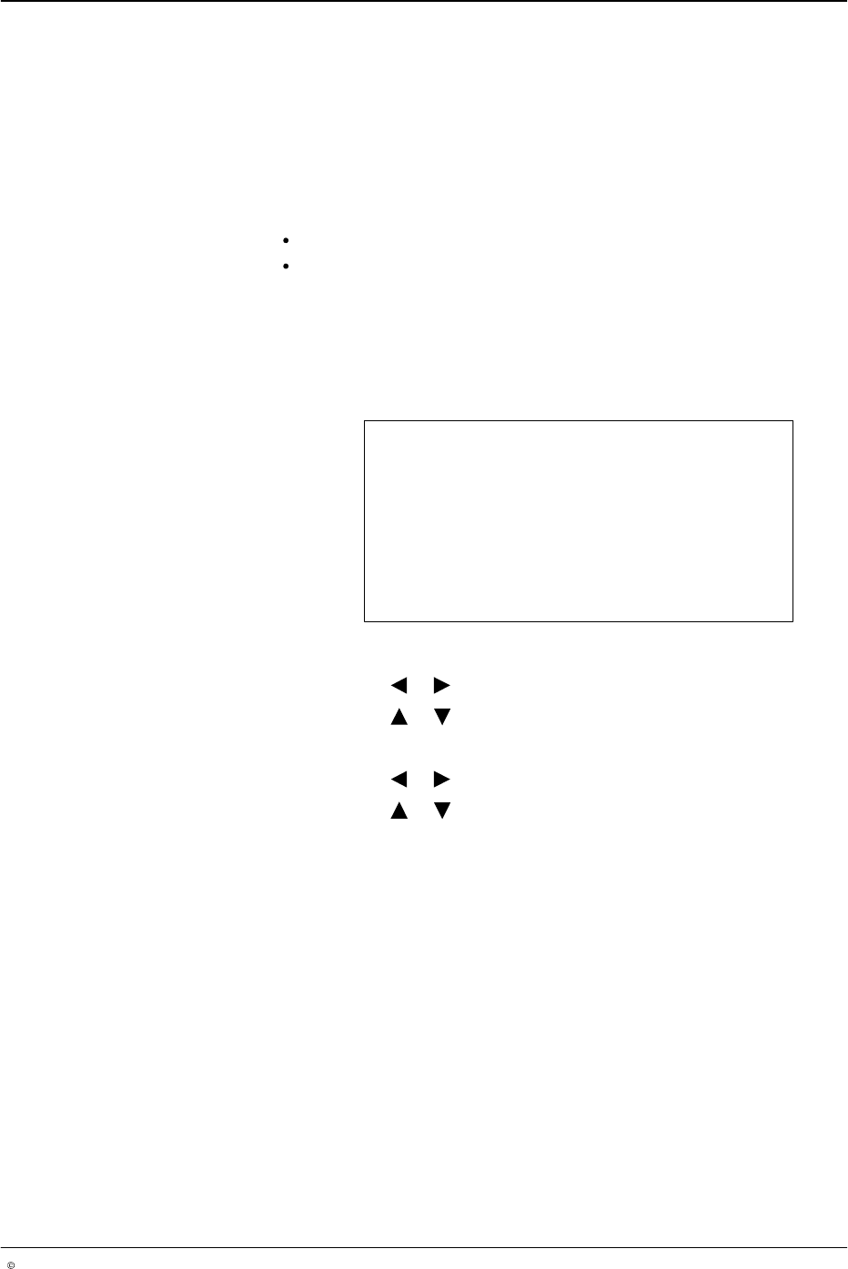
Tip Sealer Settings
Mode Automatic
Dwell time 3.0 s
O687
1. To set tip sealer mode
a. Press the or button for the cursor to appear beside Mode.
b. Press the or button to Forced Open or Automatic.
2. To set Dwell time
a. Press the or button for the cursor to appear beside Dwell time.
b. Press the or button to set the numeric value from 0.0 - 99.0 s.