Specification SIPLACE X-Series规格说明书1.pdf - 第11页
11 Machine Performance SIPLACE X3 placement system For the placement head confi guration a nd the placement rate see the n ote on page 10. Number of gantries 3 Placement area 1 Placement area 2 IPC value Benchmark value …

10
Machine Performance
Types of placement
head
20-nozzle Collect&Place head (C&P20)
12-nozzle Collect&Place head (C&P12)
6-nozzle Collect&Place head (C&P6)
SIPLACE TwinHead (TH)
PLEASE NOTE IPC value [comp./h]
According to the vendor-neutral conditions of the IPC 9850 standard pub-
lished by the Association of Connecting Electronics Industries.
SIPLACE Benchmark value [comp./h]
The SIPLACE benchmark value is measured during the machine accep-
tance tests. It corresponds to the conditions set out in the SIPLACE scope of
service and supply.
Theoretical maximum output value [comp./h]
The theoretical maximum output value is calculated from the most favorable
conditions for each machine type and setting, and corresponds to the theo-
retical conditions normally used in the industry.
SIPLACE X4 placement system
Number of gantries 4
Placement area 1 Placement area 2 IPC value Benchmark value Theoretical value
C&P20 / C&P20 C&P20 / C&P20 81,000 90,000 124,000
C&P20 / C&P20 C&P12 / C&P12 65,000 71,400 102,500
C&P20 / C&P20 C&P12 / C&P6 60,300 65,300 94,000
C&P20 / C&P20 C&P12 / TH 57,500 63,800 89,000
C&P20 / C&P20 C&P6 / C&P6 56,900 63,300 85,000
C&P20 / C&P20 C&P6 / TH 53,100 59,400 80,000
C&P20 / C&P20 TH / TH 47,800 52,500 75,000
C&P12 / C&P12 C&P12 / C&P12 49,000 52,800 81,500
C&P12 / C&P12 C&P12 / C&P6 44,300 46,700 72,500
C&P12 / C&P12 C&P12 / TH 41,500 45,200 67,500
C&P12 / C&P12 C&P6 / C&P6 40,900 44,700 64,000
C&P12 / C&P12 C&P6 / TH 37,100 40,800 59,000
C&P12 / C&P12 TH / TH 31,800 33,900 53,500
C&P12 / C&P6 C&P12 / C&P6 39,600 40,600 64,000
C&P12 / C&P6 C&P12 / TH 36,800 39,100 59,000
C&P12 / C&P6 C&P6 / C&P6 36,200 38,600 55,000
C&P12 / C&P6 C&P6 / TH 32,400 34,700 50,000
C&P12 / C&P6 TH / TH 27,100 27,800 45,000
C&P12 / TH C&P12 / TH 34,000 37,600 53,500
C&P12 / TH C&P6 / TH 29,600 33,200 45,000
C&P12 / TH TH / TH 24,300 26,300 40,000
C&P6 / C&P6 C&P6 / C&P6 32,800 36,600 46,000
C&P6 / C&P6 C&P6 / TH 29,000 32,700 41,000
C&P6 / C&P6 TH / TH 23,700 25,800 36,000
C&P6 / TH C&P6 / TH 25,200 28,800 36,000
C&P6 / TH TH / TH 19,900 21,900 31,000
TH / TH TH / TH 14,600 15,000 26,000

11
Machine Performance
SIPLACE X3 placement system
For the placement head configuration and the placement rate see the note on page 10.
Number of gantries 3
Placement area 1 Placement area 2 IPC value Benchmark value Theoretical value
C&P20 / C&P20 C&P20 62,200 69,500 93,000
C&P20 / C&P20 C&P12 53,600 59,000 82,500
C&P20 / C&P20 C&P6 49,200 54,800 73,500
C&P20 / C&P20 TH 44,800 50,000 68,500
C&P12 / C&P12 C&P12 37,600 40,400 61,000
C&P12 / C&P12 C&P6 33,200 36,200 52,500
C&P12 / C&P12 TH 28,800 31,400 47,000
C&P12 / C&P6 C&P6 28,500 30,100 43,500
C&P12 / C&P6 TH 24,100 25,300 38,500
C&P12 / TH TH 21,300 23,800 33,500
C&P6 / C&P6 C&P6 25,100 28,100 34,500
C&P6 / C&P6 TH 20,700 23,300 29,500
C&P6 / TH TH 16,900 19,400 24,500
TH / TH TH 11,600 12,500 19,500
SIPLACE X2 placement system
For the placement head configuration and the placement rate see the note on page 10.
Number of gantries 2
Placement area 1 Placement area 2 IPC value Benchmark value Theoretical value
C&P20 C&P20 43,400 49,000 62,000
C&P20 C&P12 34,800 38,500 51,000
C&P20 C&P6 30,400 34,300 42,500
C&P20 TH 26,000 29,500 37,500
C&P12 C&P12 26,200 28,000 40,500
C&P12 C&P6 21,800 23,800 32,000
C&P12 TH 17,400 19,000 26,500
C&P6 C&P6 17,400 19,600 23,000
C&P6 TH 13,000 14,800 18,000
TH TH 8,600 10,000 13,000
12
Placement Heads
Overview
Head Modularity
The SIPLACE X series is
characterized by maximum
flexibility in the production
process. This flexibility is
partly due to the head modu-
larity of the placement
machines as it allows differ-
ent placement head variants
to be configured to suit the
production requirements.
Collect&Place principle
The SIPLACE 20, 12 and 6-
nozzle Collect&Place heads
work on the Collect&Place
principle. This means that,
within each cycle, 20, 12 or 6
components are picked up
and “collected” by the place-
ment head, are optically cen-
tered on the way to the board
and are rotated into the
required placement angle.
They are then placed gently
and accurately on the PCB.
This principle is particularly
suitable for the high-speed
placement of standard com-
ponents.
Collect&Place principle
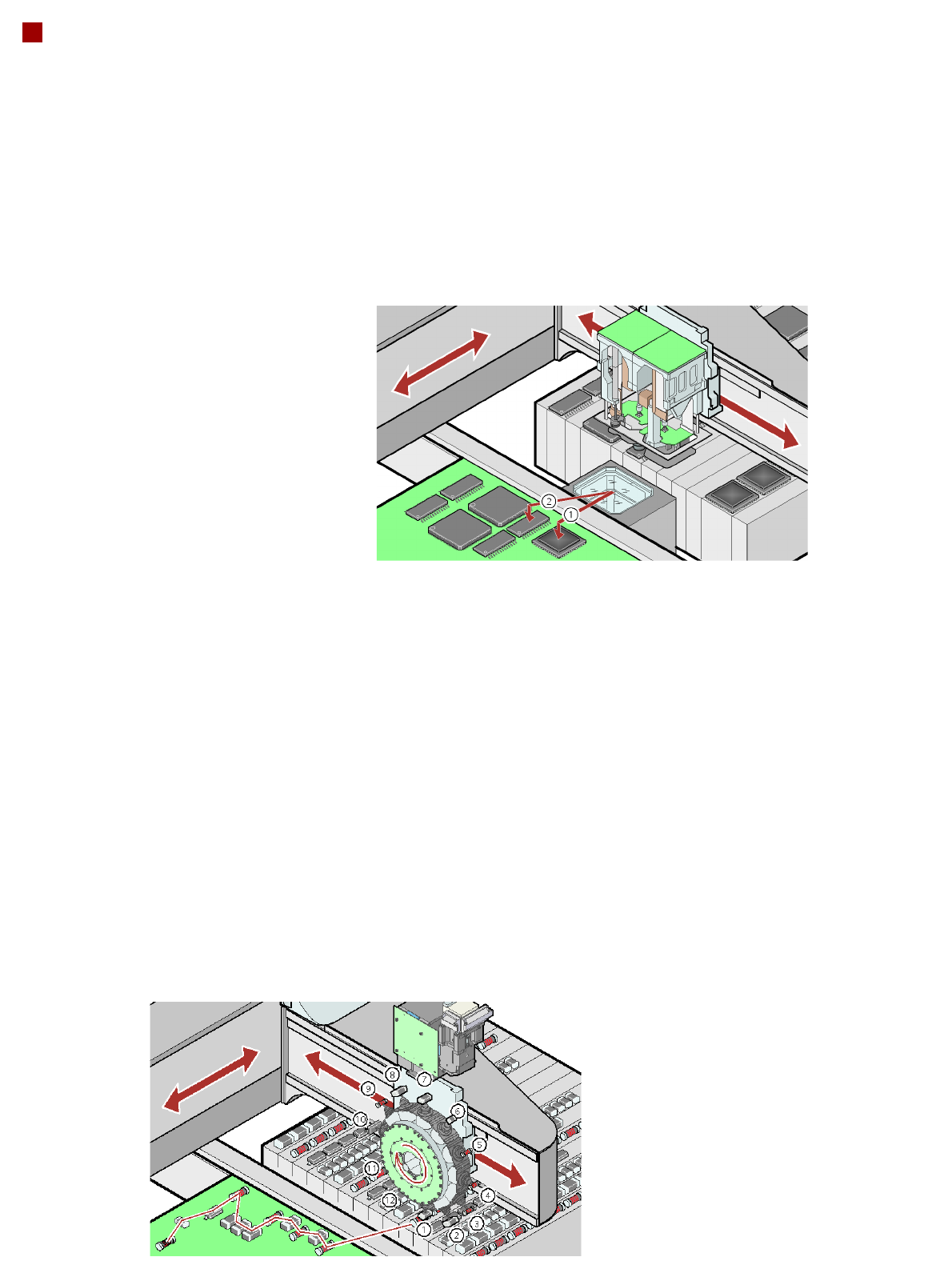
Pick&Place principle
The high-precision SIPLACE
TwinHead, which consists of
two Pick&Place placement
modules of the same design
coupled together, works on
the Pick&Place principle.
Two components are picked
up by the placement head,
optically centered on the way
to the placement position
and rotated into the neces-
sary placement angle. This
principle has proved particu-
larly suitable for fast and
accurate placement of spe-
cial components in the fine
pitch and super-fine pitch
range, and for complex and
heavy components that
require grippers, for
example.
Checking and self-learning
functions
The SIPLACE placement
heads' reliability can be fur-
ther increased with various
checking and self-learning
functions.
• Component sensor: It
checks for the presence of
a component at the nozzle
before and after the pick-
up and placement pro-
cess.
• Digital camera on the
placement head: Checks
the position of each com-
ponent at the nozzle. Any
deviations from the
required pick-up position
are corrected before
placement takes place.
• Force sensor: Monitors
the specified component
set-down forces. With the
sensor stop method, dif-
ferences in height during
pick-up and any uneven-
ness of the PCB surface
are compensated during
placement.
• Vacuum sensor: Checks
whether the component
was picked up or set down
correctly.