Specification SIPLACE X-Series规格说明书1.pdf - 第15页
15 Placement Heads TwinHead T winHead Fine-pitch camera a (component camera type 33) a) A maximum of two stationary cameras can be configured in one placement area. TwinHead Flip-chip camera (option) a (component camera …
14
Placement Heads
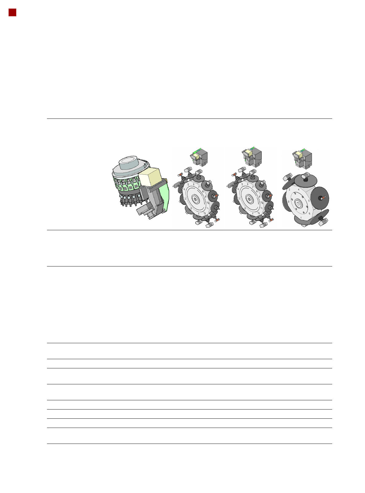
Collect&Place Heads
20-nozzle
Collect&Place head
CO camera type 23
12-nozzle
Collect&Place head
CO camera type 28
12-nozzle
Collect&Place head
CO camera type 29
6-nozzle
Collect&Place head
CO camera type 29
Component range
a
a) Please note that the range of components that can be placed is also affected by the pad geometry, customer-specific
standards, component packaging tolerances and component tolerances.
01005 to 2220, Melf,
SOT, SOD
0402 to PLCC44,
BGA, µBGA, flip-
chip, TSOP, QFP,
SO to SO32, DRAM
0201
b
to flip-chip,
bare die, PLCC44,
BGA, µBGA, TSOP,
QFP, SO to SO32,
DRAM
b) With 0201 package.
0201 to 27 x 27 mm²
Component spec.
max. height
min. lead pitch
min. lead width
min. ball pitch
min. ball diameter
min. dimensions
max. dimensions
max. weight
4 mm
0.25 mm
0.1 mm
0.4 mm
0.2 mm
0.4 x 0.2 mm²
6 x 6 mm²
1 g
6 mm
0.5 mm
0.2 mm
0.35 mm
0.2 mm
1.0 x 0.5 mm²
18.7 x 18.7 mm²
2 g
6 mm
0.3 mm
0.15 mm
0.25 mm
0.14 mm
0.6 x 0.3 mm²
18.7 x 18.7 mm²
2 g
8.5 mm
0.3 mm
0.15 mm
0.25 mm
c
0.35 mm
d
0.14 mm
c
0.2 mm
d
0.6 x 0.3 mm²
27 x 27 mm²
5 g
c) For components < 18 x 18 mm².
d) For components 18 x 18 mm².
Programmable set-down
force
1.5 N - 4.5 N 2.4 N - 5.0 N 2.4 N - 5.0 N 2.4 N - 5.0 N
Nozzle types 10xx, 11xx, 12xx 9xx 9xx 8xx, 9xx
X/Y accuracy
e
e) The accuracy value was measured using the vendor-neutral IPC standard.
± 41 µm/3
± 55 µm/4
± 45 µm/3
± 60 µm/4
± 41 µm/3
± 55 µm/4
± 45 µm/3
± 60 µm/4
Angular accuracy ± 0.5° / 3
± 0.7° / 4
± 0.5° / 3
± 0.7° / 4
± 0.5° / 3
± 0.7° / 4
± 0.2° / 3
± 0.3° / 4
Component range 95% 98% 98.5% 99.5%
Component camera type 23 28 29 29
Illumination levels 5 5 5 5
Possible lighting level
settings
256
5
256
5
256
5
256
5
15
Placement Heads
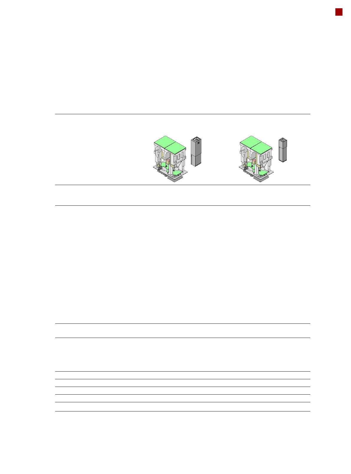
TwinHead
TwinHead
Fine-pitch camera
a
(component camera type 33)
a) A maximum of two stationary cameras can be configured in one placement area.
TwinHead
Flip-chip camera (option)
a
(component camera type 25)
Component range
b
b) Please note that the range of components that can be placed is also affected by the pad geometry, customer-
specific standards, component packaging tolerances and component tolerances.
0402 to SO, PLCC, QFP, BGA,
special components, bare dies,
flip-chips
0201 to SO, PLCC, QFP, sockets,
plugs, BGA, special components,
bare dies, flip-chips, shields
Component specs
c
max. height
min. lead pitch
min. lead width
min. ball pitch
min. ball diameter
min. dimensions
max. dimensions
max. weight
d
c) If the C&P head and the TwinHead are combined in one placement area, the maximum component height is
restricted.
d) If standard nozzles are used.
25 mm (larger heights on request)
0.3 mm
0.15 mm
0.35 mm
0.2 mm
1.0 x 0.5 mm²
55 x 45 mm²
(single measurement)
For use with two nozzles
50 x 50 mm² or
69 x 10 mm²
For use with one nozzle:
85 x 85 mm² or
125 x 10 mm²
max. 200 x 125 mm² (with restric-
tions)
100 g
25 mm (larger heights on request)
0.25 mm
0.1 mm
0.14 mm
0.08 mm
0.6 x 0.3 mm²
16 x 16 mm²
(single measurement)
100 g
Programmable set-down force 1.0 N - 15 N
2.0 N - 30 N
e
e) SIPLACE High-Force Head.
1.0 N - 15 N
2.0 N - 30 N
e
Nozzle types
f
f) Over 300 different nozzles and 100 gripper types are available, with an extensive nozzle database available
online.
5xx (standard)
4xx + adapter
8xx + adapter
9xx + adapter
gripper
5xx (standard)
4xx + adapter
8xx + adapter
9xx + adapter
gripper
Nozzle spacing for P&P heads 70.8 mm 70.8 mm
X/Y accuracy
g
g) The accuracy value was measured using the vendor-neutral IPC standard.
± 26 µm/3± 35 µm/4 ± 22 µm/3± 30 µm/4
Angular accuracy ± 0.05° / 3± 0.07°/ 4 ± 0.05° / 3± 0.07° / 4
Illumination levels 6 6
Possible lighting level settings
256
6
256
6
16
Placement Heads
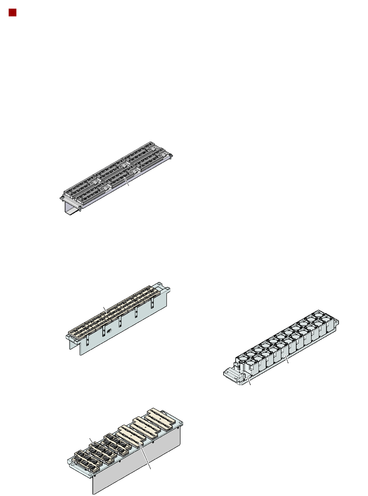
Nozzle Changer
Magazine for 6
type 9xx nozzles
Magazine for 12
type 9xx nozzles
Nozzle changer for the
12-nozzle Collect&Place head (NCH12)
(5 magazines in total
60 nozzle holders)
Nozzle changer for the
6-nozzle Collect&Place head (NC6)
(6 magazines in total 36 nozzle holders)
Magazine for two
standard nozzles
Magazine for one
special nozzle, gripper
Nozzle changer
for the TwinHead
Magazine for 6
type 8xx nozzles
Nozzle changer for the
20-nozzle Collect&Place head (NCH20)
(6 magazines in total
72 nozzle holders)
Magazine for 12
type 10xx, 11xx or 12xx
nozzles
Description
Nozzle changers increase
the flexibility of placement
heads when processing dif-
ferent components. The
nozzle configuration can be
quickly modified for new
placement jobs. Exactly
defined positions and the per-
fect seating of the nozzle in
the garage guarantee mini-
mal radial eccentricity at the
placement head.
The nozzle changer for the
20-nozzle Collect&Place
head is equipped with a mon-
itoring circuit which checks
whether the nozzle magazine
is seated correctly on the
mount.