Specification SIPLACE X-Series规格说明书1.pdf - 第17页
17 Placement Heads Nozzle Changer Technical Data The number of nozzle changers for the Collect & Place heads depends on the number of gantries in the place- ment area: - up to four nozzle changers may be installed in…
16
Placement Heads
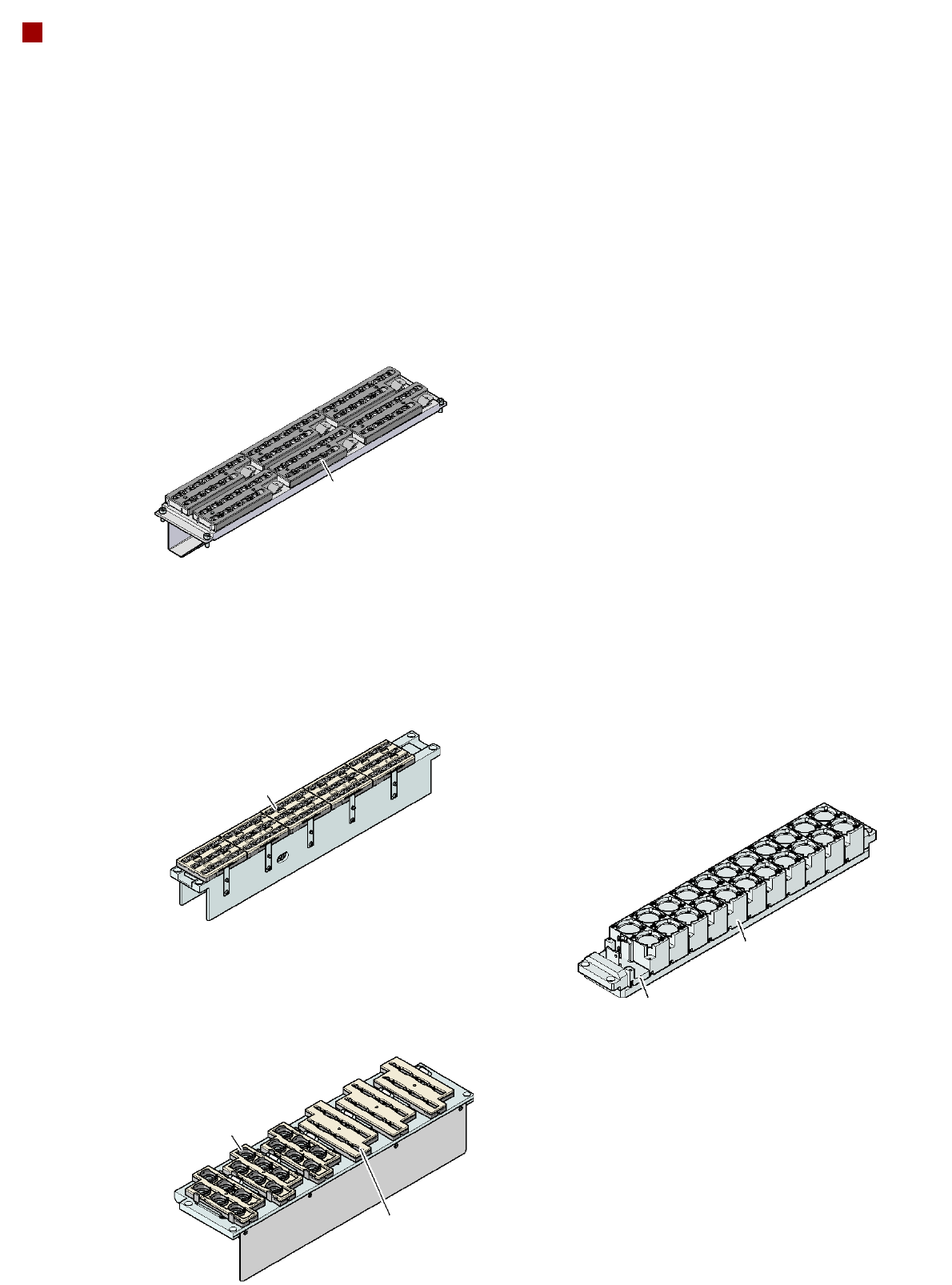
Nozzle Changer
Magazine for 6
type 9xx nozzles
Magazine for 12
type 9xx nozzles
Nozzle changer for the
12-nozzle Collect&Place head (NCH12)
(5 magazines in total
60 nozzle holders)
Nozzle changer for the
6-nozzle Collect&Place head (NC6)
(6 magazines in total 36 nozzle holders)
Magazine for two
standard nozzles
Magazine for one
special nozzle, gripper
Nozzle changer
for the TwinHead
Magazine for 6
type 8xx nozzles
Nozzle changer for the
20-nozzle Collect&Place head (NCH20)
(6 magazines in total
72 nozzle holders)
Magazine for 12
type 10xx, 11xx or 12xx
nozzles
Description
Nozzle changers increase
the flexibility of placement
heads when processing dif-
ferent components. The
nozzle configuration can be
quickly modified for new
placement jobs. Exactly
defined positions and the per-
fect seating of the nozzle in
the garage guarantee mini-
mal radial eccentricity at the
placement head.
The nozzle changer for the
20-nozzle Collect&Place
head is equipped with a mon-
itoring circuit which checks
whether the nozzle magazine
is seated correctly on the
mount.

17
Placement Heads
Nozzle Changer
Technical Data
The number of nozzle changers for the Collect&Place heads depends on the number of gantries in the place-
ment area:
- up to four nozzle changers may be installed in the placement area with two gantries.
- up to three nozzle changers may be installed in the placement area with one gantry.
Nozzle changer for the 20-nozzle Collect&Place head
Dimensions (length x width x height) 449 x 94.5 x 79 mm³
Number of magazines 6, each with 12 nozzle holders
a
a) All 6 magazines must always be set up.
Number of nozzle holders 72
Nozzle types 10xx, 11xx, 12xx
Compressed air connection 0.48 MPa (4.8 bar)
Nozzle changer for the 12-nozzle Collect&Place head
Dimensions (length x width x height) 449 x 62.7 x 77.7 mm³
Number of magazines min. 1 / max. 5, each with 12 nozzle holders
Nozzle types 9xx
Compressed air connection 0.48 MPa (4.8 bar)
Nozzle changer for the 6-nozzle Collect&Place head
Dimensions (length x width x height) 448 x 122.5 x 97.7 mm³
Number of magazines min. 1 / max. 6, each with 6 nozzle holders
Nozzle types 8xx, 9xx
Compressed air connection 0.48 MPa (4.8 bar)
Nozzle changers for the SIPLACE TwinHead
Dimensions (length x width x height) 448 x 68.5 x 49 mm³
Number of magazines a maximum of 12, each with two nozzle holders
at locations 1 and 3
a maximum of 10, each with two nozzle holders
at locations 2 and 4
Number of nozzle holders may be freely configured
Nozzle types
b
b) Over 300 different nozzles and 100 gripper types are available, with an extensive nozzle database avail-
able online.
4xx with adapter
5xx (standard)
9xx with adapter
Special nozzle, gripper
18
PCB Conveyor
Single Conveyor and Dual Conveyor
Conveyor principle
If the board has reached the
placement area and passed
a light barrier, it is braked. An
additional laser light barrier
determines the position of
the board. As soon as the cir-
cuit board has reached its
target position, the conveyor
belt is stopped and the board
is clamped from below. The
placement process then
starts immediately. Move-
ment and clamping of the
PCBs are monitored.
The conveyor can be easily
matched to many different
PCB widths by the automatic
electrical width adjustment.
The fixed conveyor rail may
be located on the left or right
for both the flexible dual con-
veyor and the single con-
veyor.
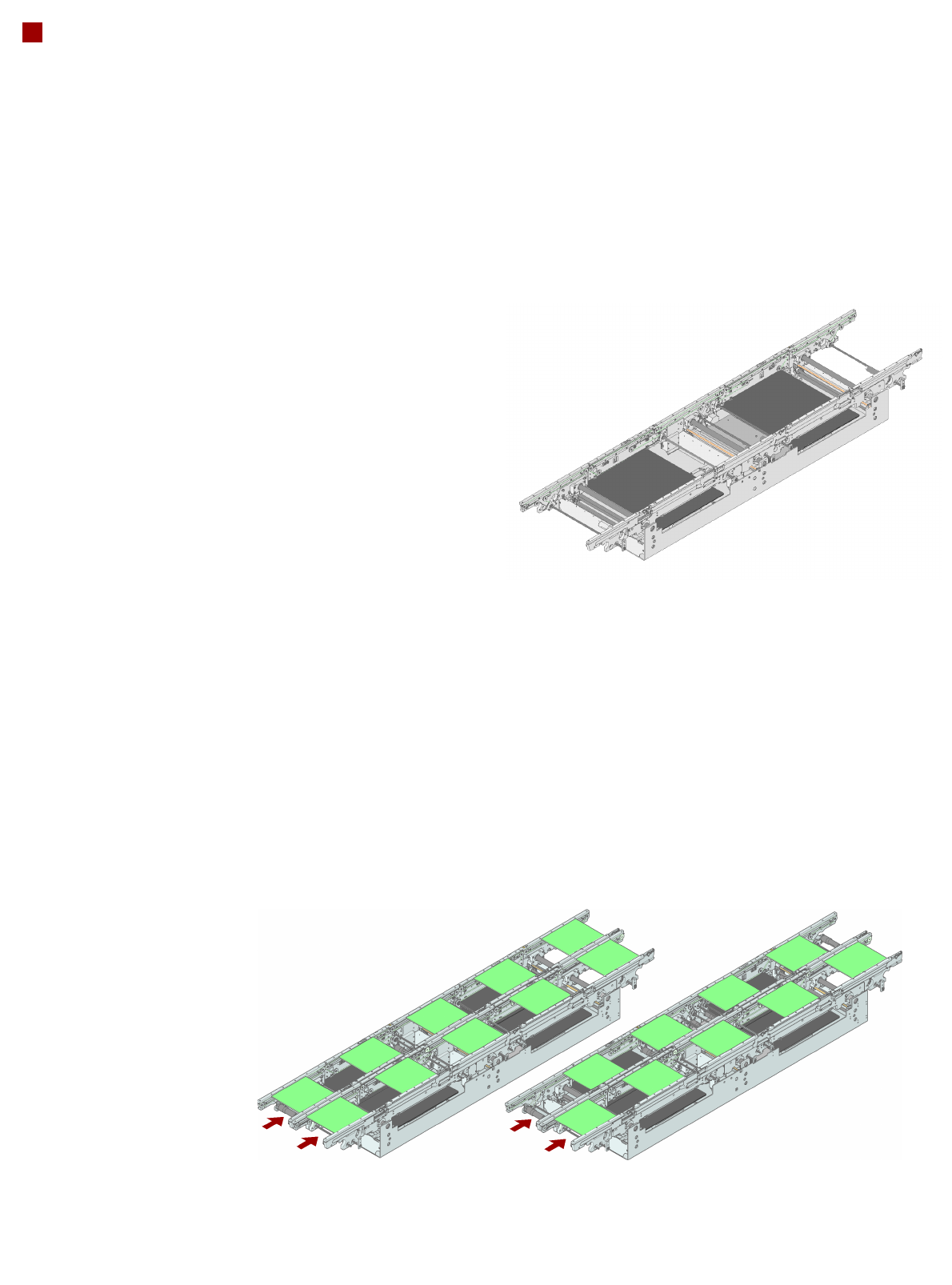
Single conveyor
On the single conveyor,
PCBs are moved one after
the other into the placement
machine and placed on a
conveyor track. This con-
veyor variant is particularly
suitable for very wide PCBs.
Flexible dual conveyor
To keep the range of PCBs to
be processed as wide as
possible - whilst maintaining
maximum productivity -
the flexible SIPLACE
dual conveyor
allows you to
choose between single con-
veyor mode and dual con-
veyor mode.
In dual conveyor mode, two
PCBs are moved into the
placement machine and
placed either simultaneously
(synchronous operation)
or alternately (asyn-
chronous opera-
tion).
In synchronous mode,
two PCBs are moved into
the placement position at the
same time. They are pro-
cessed as a common panel.
This allows the top and bot-
tom of PCB to be processed
on the same line and, for
products with very different
components to be placed,
the common optimization of
all the components to be
placed on both PCBs makes
it possible to increase output.
In asynchronous mode,
only one PCB in a transport
track is processed. At the
same time, another PCB in
the second transport track is
moved into the placement
position. This saves
the full conveying
time of one
PCB, thus considerably
increasing performance,
particularly for
PCBs with a
short cycle
time. The
placement
process starts as
soon as one PCB is trans-
ported into the processing
area.
Conveyor buffer
SIPLACE PCB conveyors
have three buffer zones. If
shorter waiting times occur in
a placement area (due to lon-
ger cycle times in the oven,
for example), the down-
stream placement areas can
continue to work since the
unaffected area can easily
access the PCB that is wait-
ing in the buffer zone. This
increases the true output of
the placement line.
Flexible dual conveyor:
synchronous mode
Flexible dual conveyor:
asynchronous mode