Specification SIPLACE X-Series规格说明书1.pdf - 第24页
24 PCB Barcode for Product-Controlled Production (Option) Label dimensions S troke width (W): 0.19 < W 0.3 mm (corresponds to high and medium density), S troke length: mm, length of the barcode template windo…
23
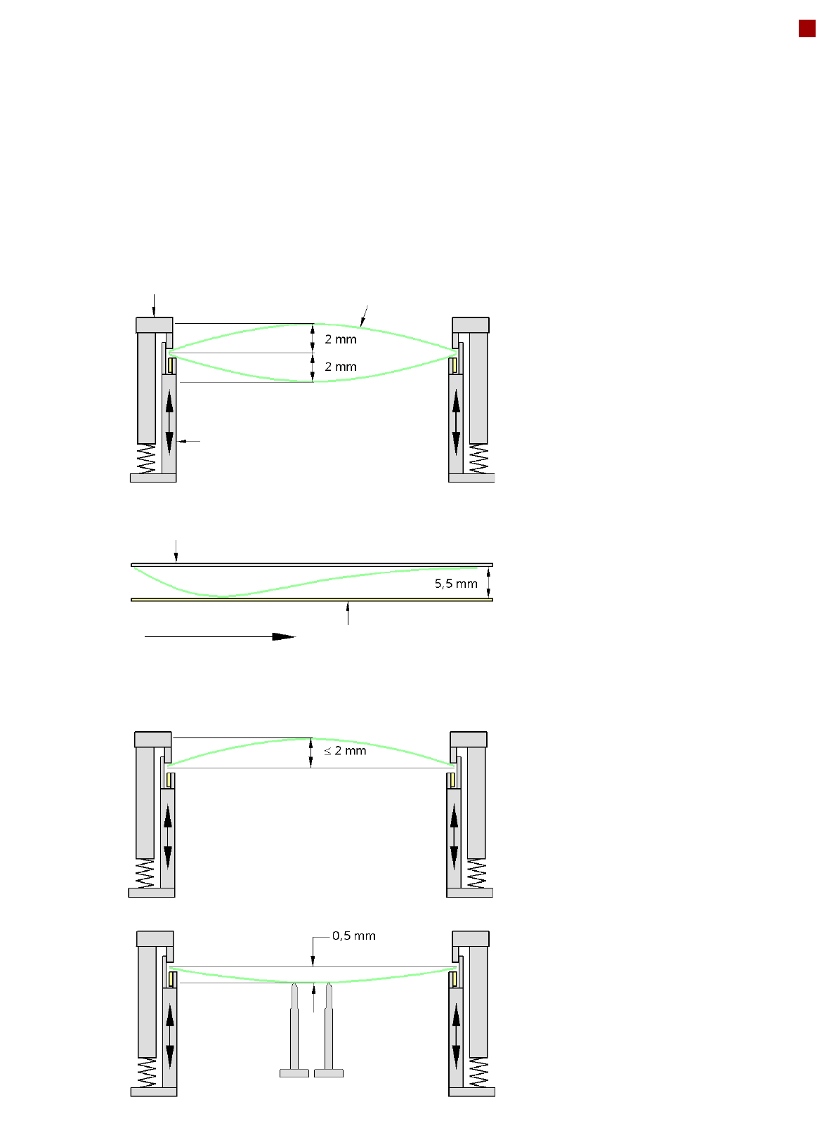
PCB Warpage
PCB warpage across the direction of travel
max. 1 % of the PCB diagonal, but not
exceeding 2 mm
PCB warpage on the conveyor
PCB warpage during placement
PCB transport direction
PCB warpage downwards, max. 0.5 mm
Use magnetic pin supports to achieve this
value.
Conveyor belt
Fixed clamped edge
PCB warpage in direction of travel
+ PCB thickness < 5.5 mm
Fixed clamped edge
Movable clamping device
For warpage of less than 2 mm, the ink
spots are also in the middle of the PCB in
the digital camera's focus. When all the tol-
erances are taken into account, this value is
reduced to 1.5 mm.
You should also note that the warpage
reduces the component height.
Magnetic pin support
PCB
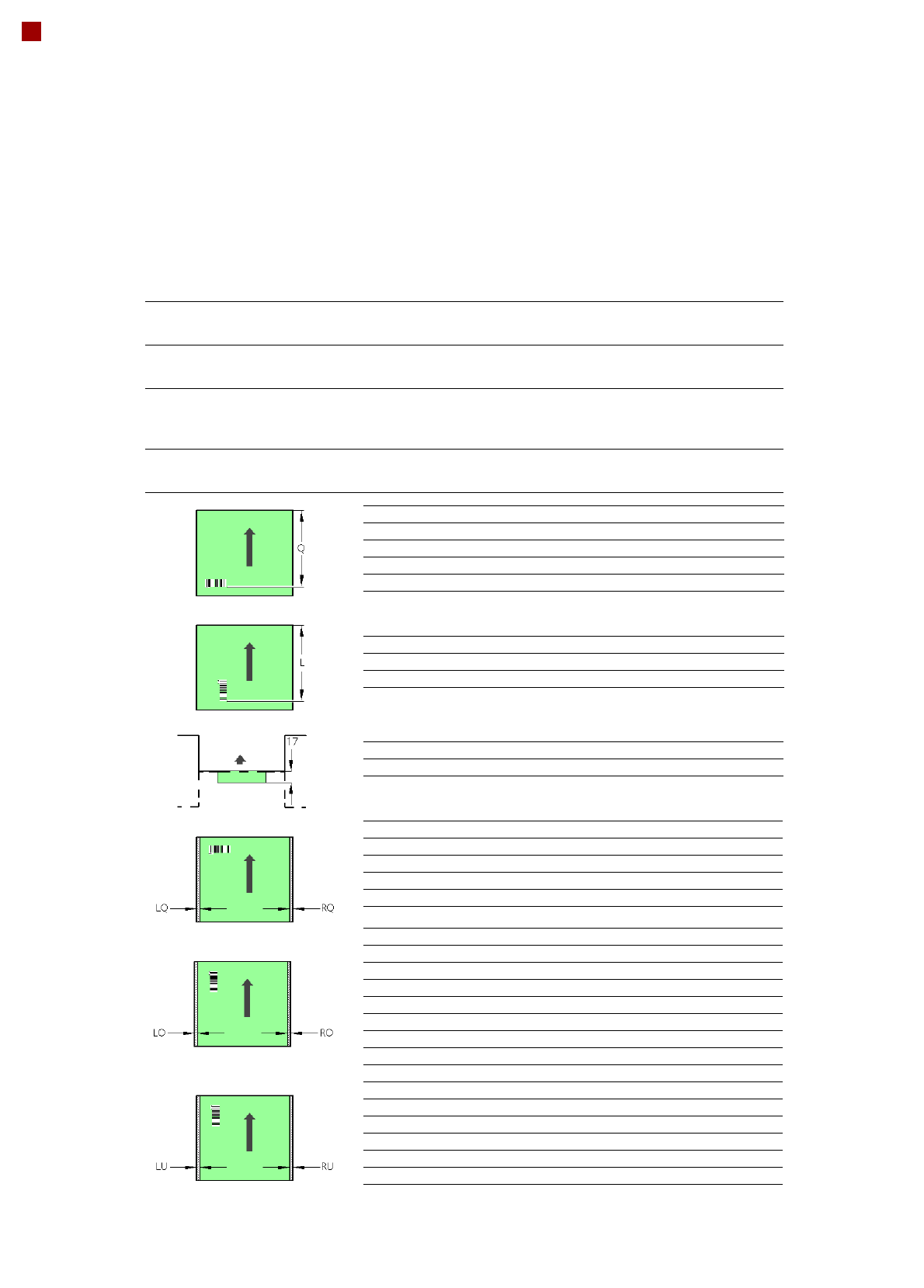
24
PCB Barcode for Product-Controlled Production
(Option)
Label dimensions Stroke width (W): 0.19 < W 0.3 mm (corresponds to high and medium density),
Stroke length: mm, length of the barcode template window: 90 mm
Recommended label
colors
Coding: black, dark green, dark blue, background: white, beige, yellow, orange
(contrast ratio > 70% to DIN 66236)
Code types Code 39, Code 128 / EAN 128, Codabar, 2/5 IATA 2/5 industrial, 2/5 interleaved,
UPC, EAN, Pharma Code, EAN Addendum (others available on request), a bar-
code filter may be defined
Laser scanner safety Laser diode 670 nm (red) / 1.2 mW
Laser protection class 2, degree of protection IP65
Downstream
machine
Upstream
machine
PCB
PCB barcode scanner 1D on top
PCB barcode scanner 1D on bottom
PCB barcode scanner Q [mm]
2D topside 390
1D topside 390
2D underside 430
1D underside 430
PCB barcode scanner L [mm]
1D topside 320 - 350
1D underside 380 - 410
PCB barcode scanner PCB rear projection [mm]
2D underside on the dual conveyor 17
PCB barcode scanner LQ [mm] RQ [mm]
2D topside 3 3
1D topside 3 3
2D underside 5 5
1D underside 5 5
PCB dimensions/conveyor LO [mm] RO [mm]
460 mm SC 3 20
508 mm SC 3 44
216 mm DC1 3 24
250 mm DC1, 450 mm SM1 3 58
216 mm DC2 3 3
250 mm DC2, 450 mm SM2 3 3
PCB dimensions/conveyor LU [mm] RU [mm]
460 mm SC 20 3
508 mm SC 44 3
216 mm DC1 3 3
250 mm DC1, 450 mm SM1 3 3
216 mm DC2 24 3
250 mm DC2, 450 mm SM2 58 3
SC - Single conveyor, DC1/2 - Dual conveyor, track 1/2, SM1/2 - Dual conveyor in Single conveyor mode, track 1/2
If there is a PCB dual conveyor installed on the placement machine, we can provide a special design for
retrofitting the 2D PCB barcode scanner “bottom”.
25
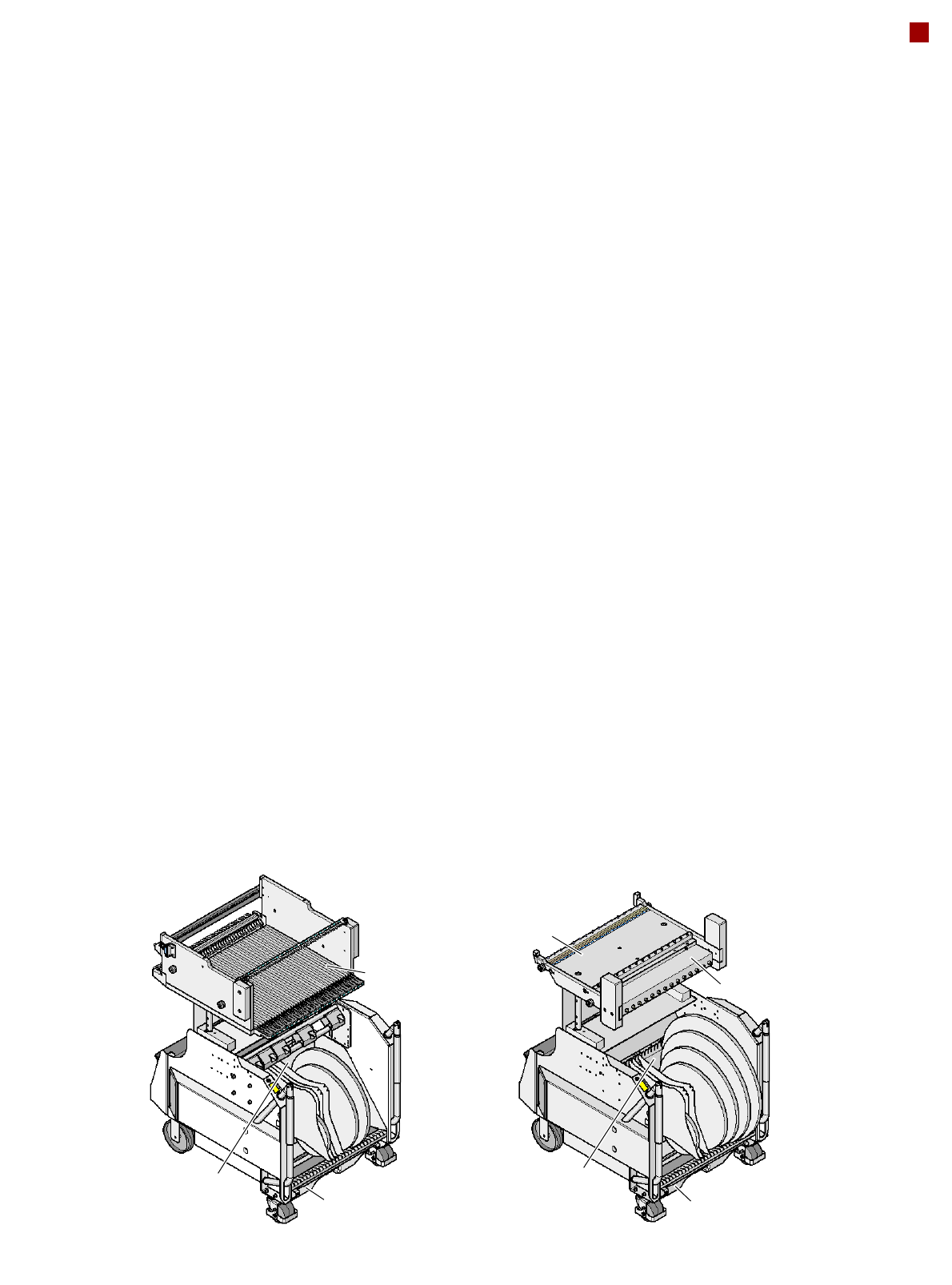
Component Feeding
Component Changeover Table
SIPLACE X component
changeover table
The SIPLACE X component
changeover tables are stand-
alone and easily maneuver-
able modules that are moved
into the machine with the
automatic docking unit. This
ensures that the table is
accurately positioned in the
placement machine. Reels
are kept in the tape container
on the component change-
over table.
A cutting device on the
machine automatically cuts
the used tape. The compo-
nent changeover tables can
be set up directly on the
machine or in an external
set-up area with feeder mod-
ules. The benefits of offline
set-up are that the set-ups
can be prepared without
stopping the line. This allows
the set-up to be changed
very quickly using the
changeover table principle.
The SIPLACE X component
changeover table also sup-
port extremely high-speed
attachment and removal of
the feeder modules while the
placement process is run-
ning. The component feed-
ers are at rest during the
placement process - allowing
tapes to be spliced without
stopping the machine.
If an optional component bar-
code reader and the Setup
Center option are installed, it
is possible to read and check
the barcodes on the tape
reels. This makes sure that
the component is allocated to
the right track, and the PCB
placement can be traced
using traceability software.
Dummy feeder modules are
used at unassigned locations
to protect the operators.
SIPLACE HF component
changeover table
The SIPLACE HF compo-
nent changeover table can
also be used on SIPLACE
X2, X3 and X4 machines,
which means that all S tape
feeder modules and all other
feeder modules from this
generation can still be used.
This ensures maximum pro-
tection for your investment.
You must make sure, how-
ever, that the appropriate
docking unit is fitted for com-
ponent changeover tables
from the SIPLACE HF series.
The SIPLACE HF series
component changeover table
also cannot be used with the
20-nozzle Collect&Place
head.
Communication unit
Waste container
for remaining empty tape
Component
table
Tape container
SIPLACE X
component changeover table
SIPLACE HF
component changeover table
Waste container
for remaining empty tape
Component
table
Tape container