Specification SIPLACE X-Series规格说明书1.pdf - 第40页
40 Vision Sensor Technology 2D Coplanarity Laser Module See page 39 for a de scription of the copla narity proper ties. Measuring principle Measurement of the heights of the conn ections occu rs contact-free accordin g t…
39
Vision Sensor Technology
3D Coplanarity Laser Module
Technical data
Components QFP, SO, BGA, gull-wing,
plug
Accuracy
a
a) Per ball / lead.
± 15 µm (3
± 20 µm (4
Max. component size 50 x 50 mm²
Max. connector size 120 x 20 mm²
min. ball diameter / distance 400 µm / 800 µm
Min. number of balls 6
Min. lead width / pitch 300 µm
b
/ 500 µm
b) Please contact your local product manager in the case of
smaller lead widths.
Min. lead number 5
Max.
CO height
17 mm
Positioning option Location 3 on SIPLACE
X2 and X3, alternative to
the 2D coplanarity laser
module
Placement head type TwinHead
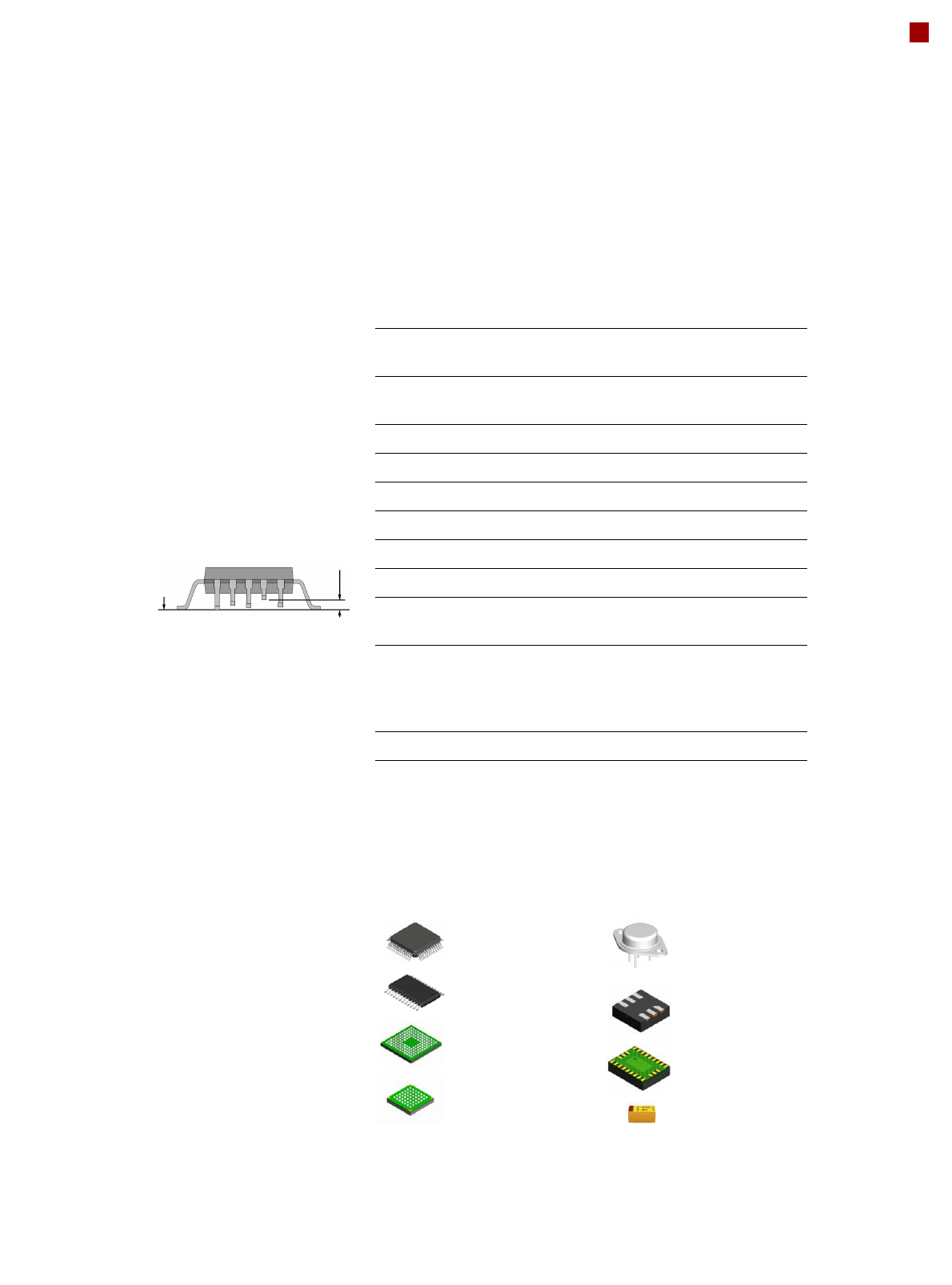
Description
Coplanarity of connections
on a component means that
all connections lie on a level,
the so-called placement
plane. This level is created
from the height information
from the coplanarity mea-
surement. This ensures that
the same soldering condi-
tions apply for all connec-
tions.
Place-
ment
Deviation from
coplanarity
Measuring principle
Measurement of the heights
of the connections occurs
contact-free according to the
principle of laser-triangula-
tion. For the 3D method, a
laser beam line scans the
component. The reflected
light from the laser is repro-
duced on a camera. In this
way the height information
for the connections is
obtained from the reflected
light from the laser.
Restrictions
• Lead or ball recognition
can get worse if the sur-
face is oxidized or glossy.
• The following components
cannot be measured: a
PLCC, SOJ, socket, chip,
bare die, Moulded, Melf,
ECV, DPack, CCGA,
screening plate, compo-
nents with internal con-
nections.
3D coplanarity module
Component inspection possible Component inspection not
possible
Only 5 pins
Lead/ball size within
specification
Also gull-wing
connections
With internal con-
nections, no gull-
wing form
The same applies to screening
plates, plugs with connections
on the underside, bare die etc.

40
Vision Sensor Technology
2D Coplanarity Laser Module
See page 39 for a description
of the coplanarity properties.
Measuring principle
Measurement of the heights
of the connections occurs
contact-free according to the
principle of laser-triangula-
tion. For the 2D method, a
point laser beam scans the
component. The reflected
light from the laser is pro-
jected onto a sensor. In this
way the height information
for the connections is
obtained from the reflected
light from the laser.
Restrictions
• The component must
have a minimum of two
and a maximum of four
rows of gull-wing leads.
• The row of leads should
be located orthogonally to
each other.
• The leads should be
trained orthogonally to the
row of leads.
• The ends of the leads lie
on a straight line.
• Measurement of compo-
nents with just one row of
leads is not possible.
Technical data
Components Gullwing
Accuracy ± 18.5 µm (3 (reference CO)
± 24.7 µm (4
± 30.5 µm (3 (CO up to 32 mm)
± 40.7 µm (4
± 31.3 µm (3 (CO up to 55 mm)
± 41.7 µm (4
Max. component size 55 x 55 mm²
Min. lead pitch 300 µm
Max. component height 25 mm
Positioning option Location 3 on SIPLACE X2 and
X3, alternative to the 3D copla-
narity laser module
Placement head type TwinHead

41
01005 Placement
The SIPLACE X-series is
designed to place 01005
components (0.4 mm x 0.2
mm) as standard. It needs to
be running the station soft-
ware version 603.01 and
SIPLACE Pro 4.1. This will
also improve the detection
capability at the associated
nozzles.
The SIPLACE component
library already contains the
contours and dimensions of
the 01005 components.
There are also specially-
developed type 1005 compo-
nent nozzles for the
SIPLACE X-series. The
shape and size of these noz-
zles is adapted for the 01005
components and - like all
other SIPLACE nozzles -
they have an extremely
wear-resistant ceramic tip
and a flexible nozzle seat.
This guarantees maximum
precision and process reli-
ability.
Optimized pick-up is guaran-
teed by the ideal feeding
conditions in the SIPLACE X
feeder module. The smaller
the elements to be picked up,
the more accurate the pick-
up must be. Even the tiniest
inaccuracy may result in
components not being
sucked up or being sucked
up incorrectly. The SIPLACE
X feeder modules are ideally
designed for this. New
motors and fewer precision
mechanical parts also help.
The tiny components can be
processed without any loss
of performance, and can be
placed with minimal spacings
and regardless of any large
components beside the
01005 component. This
equates to true 01005 capa-
bility. As a rule with 01005
placement, a finely tuned
overall 01005 process is the
basic requirement if you want
to achieve excellent results.
All the process parameters
must be optimized. The
SIPLACE team will be
pleased to advise you on
how to do this.
01005 measurement
results and ambient condi-
tions
Dpm values and pick-up
rates for 01005 placement
are highly dependent on the
measuring conditions, so it is
important to specify them
without the corresponding
ambient conditions.
The following table lists some typically values for 01005 place-
ment that can be achieved with a SIPLACE X-series if the listed
marginal conditions are fulfilled:
Machine type SIPLACE X4, X3, X2
Placement head 20-nozzle Collect&Place head
Nozzle type 1005
Feeder module type 8mm SIPLACE X tape feeder
module
Station software 603.01 or later
SIPLACE Pro 4.1 or later
Pickup rate 99.9%
Dpm rate 50
Pad width 200 µm
Distance 100 µm
Components (L x W x H) 400 x 200 x 200 µm³ (±20 µm)
Solder paste type 5
Stencil thickness 60 µm