Specification SIPLACE X-Series规格说明书1.pdf - 第22页
22 PCB Conveyor Productivity Shuttle (XPS) Technical Data Dimensions (L x W) 540 x 1000 mm² Height 965 mm for 830 mm PCB transport height 1035 mm for 900 mm PCB transport height 1065 mm for 930 mm PCB transport height 10…
21
PCB Conveyor
Productivity Lane (XPL) and Shuttle (XPS)
SIPLACE X-Series Productivity Lane (XPL)
Conveyor mode PCB width
lane 1 [mm]
PCB width
XPL [mm]
PCB width
lane 2 [mm]
XPL max. 154 max. 154 max. 154
a) Essential for use with the Productivity Lane.
b) A shuttle is necessary if machines with a stationary left or right conveyor side are mixed together in a line.
SIPLACE X-Series
Productivity Shuttle
(XPS)
a, b
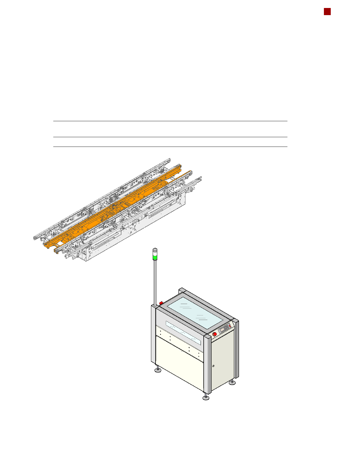
The shuttle module transfers
PCBs from up to three incom-
ing conveyor tracks to up to
three outgoing conveyor
tracks. The virtual PCB panel
coming in on a conveyor
track is transferred to an out-
going conveyor section. This
function for distributing the
PCBs on the shuttle is adjust-
able.
The “Productivity Lane”
option in the middle of the
PCB conveyor allows PCBs
to be overtaken in the place-
ment machine. As with the
Productivity Lift, the place-
ment machines are operated
in parallel. Shuttles at the
start and end of a cluster dis-
tribute the PCBs to be pro-
cessed to the required lane of
the PCB conveyor or to the
third conveyor lane.
22
PCB Conveyor
Productivity Shuttle (XPS)
Technical Data
Dimensions (LxW) 540 x 1000 mm²
Height 965 mm for 830 mm PCB transport height
1035 mm for 900 mm PCB transport height
1065 mm for 930 mm PCB transport height
1085 mm for 950 mm PCB transport height
Height with indicator lamp max. 1938 mm
Ground clearance 120 mm for 830 mm PCB transport height
190 mm for 900 mm PCB transport height
220 mm for 930 mm PCB transport height
240 mm for 950 mm PCB transport height
Weight 180 kg
Footprint 0.54 m²
Load per unit area 1.96 kN/m²
Number of machine feet 4
Maximum noise emissions 62 dB (A)
Room temperature between 15°C and 35°C
Atmospheric humidity 30 to 75 % (no higher than 45% on average to pre-
vent any possibility of condensation on the
machine)
Traversing path of the shuttle 560 mm
Number of belt segments 1
Width adjustment Stepping motor
PCB transport height 950 mm 50 mm
850 mm 50 mm (option)
PCB width 50 - 154 mm
Component-free PCB handling edge 3 mm
Interface between the input side/output side Siemens, SMEMA
Automatic tracking none
at the input side
at the output side
Electrical ratings
Supply voltage 230 VAC / 50 Hz
110 VAC / 60 Hz
Power consumption 0.4 kW
Fuses 1 x 6.3 A
23
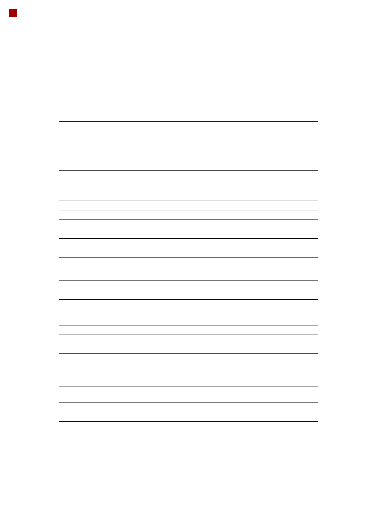
PCB Warpage
PCB warpage across the direction of travel
max. 1 % of the PCB diagonal, but not
exceeding 2 mm
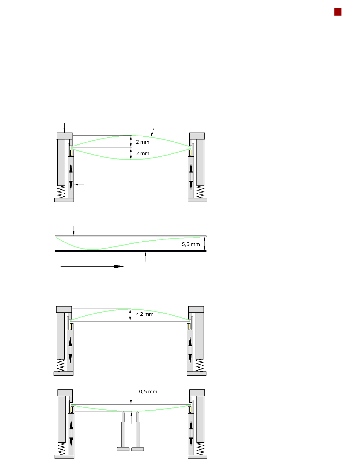
PCB warpage on the conveyor
PCB warpage during placement
PCB transport direction
PCB warpage downwards, max. 0.5 mm
Use magnetic pin supports to achieve this
value.
Conveyor belt
Fixed clamped edge
PCB warpage in direction of travel
+ PCB thickness < 5.5 mm
Fixed clamped edge
Movable clamping device
For warpage of less than 2 mm, the ink
spots are also in the middle of the PCB in
the digital camera's focus. When all the tol-
erances are taken into account, this value is
reduced to 1.5 mm.
You should also note that the warpage
reduces the component height.
Magnetic pin support
PCB