Specification SIPLACE X-Series规格说明书1.pdf - 第47页
47 Technical Data SMEMA Interface Connector Assignment Signal interface (14-p ole connecting socket, interf ace standard 1.2) Upstream station X1 Downstream station X2 Pin 1 NOT READY + Pin 1 NOT READY + Pin 2 NOT READY …

46
Maximum Quality in Production
Maximum quality in pro-
duction
The SIPLACE X-series not
only provides market-leading
machine quality; it also guar-
antees maximum product
quality through a combina-
tion of the following features:
100% placement process
control
The SIPLACE X-series has
various control mechanisms
as standard that guarantee
maximum placement reliabil-
ity. For example, sensors
check whether the compo-
nent was picked up or set
down correctly. Force sen-
sors also check the specified
component set-down forces
and compensate for differ-
ences in height during pick-
up and any bumps on the
PCB during placement.
Digital vision inspection
The digital vision system
guarantees extremely fast
and reliable component rec-
ognition, while being very
simple to use. The system
identifies each individual
component from its shape
and color. Using different illu-
mination and brightness lev-
els, almost every package
form can be easily detected.
The system also stores
images of the components,
known as “vision dumps”.
These show which compo-
nents were rejected. As a
result, errors can be detected
earlier when introducing new
products, thus increasing
process reliability. The vision
dumps also provide good
negotiation tools if defective
components are supplied.
Intelligent software for set-
up verification
The SIPLACE X series set-
ups are verified on the PCB,
on the component roll and by
the intelligent SIPLACE X
feeder modules with refer-
ence to the barcode. This
helps to avoid set-up errors.
This network of tests consid-
erably lowers dpm rates and
increases the first pass yield.
Quality values for the SIPLACE X-series
Pickup rate 99.95%
a
a) Based on average values from evaluations.
Dpm rate 3 dpm
a

47
Technical Data
SMEMA Interface
Connector Assignment
Signal interface (14-pole connecting socket, interface standard 1.2)
Upstream station X1 Downstream station X2
Pin 1 NOT READY + Pin 1 NOT READY +
Pin 2 NOT READY – Pin 2 NOT READY –
Pin 3 BOARD AVAILABLE + Pin 3 BOARD AVAILABLE +
Pin 4 BOARD AVAILABLE – Pin 4 BOARD AVAILABLE –
Pin 5 Not used Pin 5 Not used
Pin 6 Not used Pin 6 Not used
Pin 7 Not used Pin 7 Not used
Pin 8 Reserved Pin 8 Reserved
Pin 9 Reserved Pin 9 Reserved
Pin 10 Reserved Pin 10 Reserved
Pin 11 Reserved Pin 11 Reserved
Pin 12 Reserved Pin 12 Reserved
Pin 13 Reserved Pin 13 Reserved
Pin 14 Reserved Pin 14 Reserved
48
Technical Data
SMEMA Interface
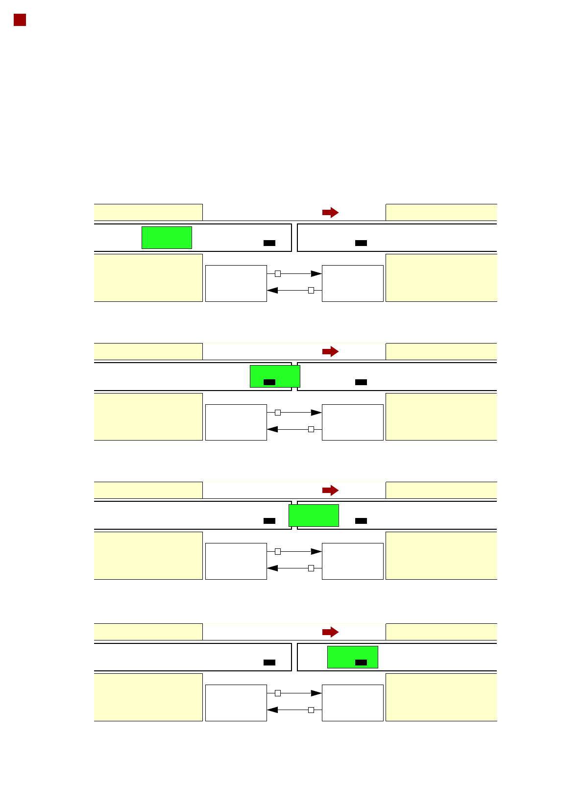
Signal Sequence
1. After switching on the station
Transport direction
Belt n Belt n+1
PCB sensor PCB sensor
Station n transports PCB
to the transfer position
Belt n running Belt n+1 stopped
BOARD AVAILABLE
Permission
Station n+1
is not ready
1
0
2. The PCB transfer has started
Transport direction
Belt n Belt n+1
PCB sensor
Station n transfers
PCB to Station n+1
Belt n running Belt n+1 running
Station n+1 expects
PCB from station n
3. PCB is transferred
Transport direction
Belt n Belt n+1
PCB sensor PCB sensor
Station n has
just transferred the PCB
Belt n stopped Belt n+1 running
Station n+1 expects PCB
from station n, but PCB
has not yet arrived.
PCB sensor
4. PCB transfer is complete
Transport direction
Belt n Belt n+1
PCB sensor PCB sensor
Station n
Belt n stopped Belt n+1 running
Station n+1
PCB arrived
Request
NOT READY
BOARD AVAILABLE
Permission
1
1
Request
NOT READY
BOARD AVAILABLE
Permission
0
1
Request
NOT READY
BOARD AVAILABLE
Permission
0
0
Request
NOT READY
To start a new PCB transfer, both signals must be “0” for at least 50 ms.