Specification SIPLACE X-Series规格说明书1.pdf - 第23页
23 PCB Warpage PCB warpage across the directio n of travel max. 1 % of the PCB diagonal, but no t exceeding 2 mm PCB warpage on the co nveyor PCB warpage during placement PCB transport directi on PCB warpage d ownwards, …
22
PCB Conveyor
Productivity Shuttle (XPS)
Technical Data
Dimensions (LxW) 540 x 1000 mm²
Height 965 mm for 830 mm PCB transport height
1035 mm for 900 mm PCB transport height
1065 mm for 930 mm PCB transport height
1085 mm for 950 mm PCB transport height
Height with indicator lamp max. 1938 mm
Ground clearance 120 mm for 830 mm PCB transport height
190 mm for 900 mm PCB transport height
220 mm for 930 mm PCB transport height
240 mm for 950 mm PCB transport height
Weight 180 kg
Footprint 0.54 m²
Load per unit area 1.96 kN/m²
Number of machine feet 4
Maximum noise emissions 62 dB (A)
Room temperature between 15°C and 35°C
Atmospheric humidity 30 to 75 % (no higher than 45% on average to pre-
vent any possibility of condensation on the
machine)
Traversing path of the shuttle 560 mm
Number of belt segments 1
Width adjustment Stepping motor
PCB transport height 950 mm 50 mm
850 mm 50 mm (option)
PCB width 50 - 154 mm
Component-free PCB handling edge 3 mm
Interface between the input side/output side Siemens, SMEMA
Automatic tracking none
at the input side
at the output side
Electrical ratings
Supply voltage 230 VAC / 50 Hz
110 VAC / 60 Hz
Power consumption 0.4 kW
Fuses 1 x 6.3 A
23
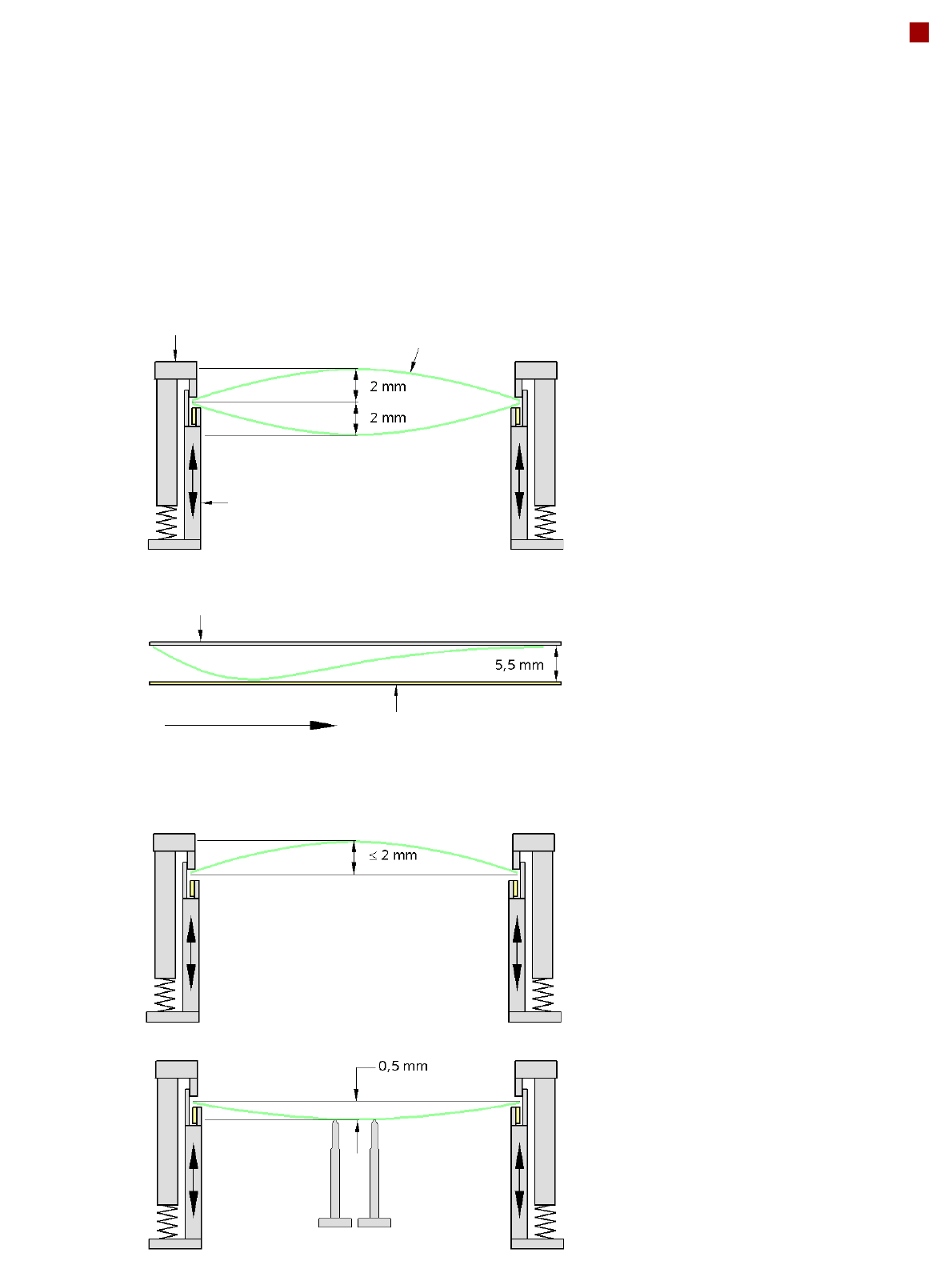
PCB Warpage
PCB warpage across the direction of travel
max. 1 % of the PCB diagonal, but not
exceeding 2 mm
PCB warpage on the conveyor
PCB warpage during placement
PCB transport direction
PCB warpage downwards, max. 0.5 mm
Use magnetic pin supports to achieve this
value.
Conveyor belt
Fixed clamped edge
PCB warpage in direction of travel
+ PCB thickness < 5.5 mm
Fixed clamped edge
Movable clamping device
For warpage of less than 2 mm, the ink
spots are also in the middle of the PCB in
the digital camera's focus. When all the tol-
erances are taken into account, this value is
reduced to 1.5 mm.
You should also note that the warpage
reduces the component height.
Magnetic pin support
PCB
24
PCB Barcode for Product-Controlled Production
(Option)
Label dimensions Stroke width (W): 0.19 < W 0.3 mm (corresponds to high and medium density),
Stroke length: mm, length of the barcode template window: 90 mm
Recommended label
colors
Coding: black, dark green, dark blue, background: white, beige, yellow, orange
(contrast ratio > 70% to DIN 66236)
Code types Code 39, Code 128 / EAN 128, Codabar, 2/5 IATA 2/5 industrial, 2/5 interleaved,
UPC, EAN, Pharma Code, EAN Addendum (others available on request), a bar-
code filter may be defined
Laser scanner safety Laser diode 670 nm (red) / 1.2 mW
Laser protection class 2, degree of protection IP65
Downstream
machine
Upstream
machine
PCB
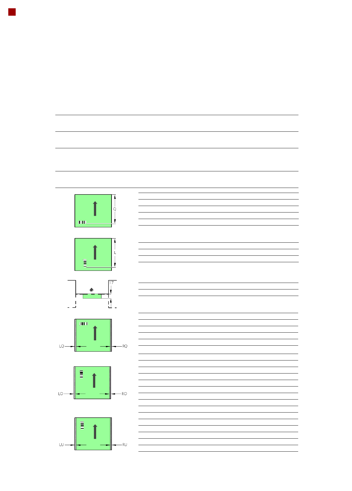
PCB barcode scanner 1D on top
PCB barcode scanner 1D on bottom
PCB barcode scanner Q [mm]
2D topside 390
1D topside 390
2D underside 430
1D underside 430
PCB barcode scanner L [mm]
1D topside 320 - 350
1D underside 380 - 410
PCB barcode scanner PCB rear projection [mm]
2D underside on the dual conveyor 17
PCB barcode scanner LQ [mm] RQ [mm]
2D topside 3 3
1D topside 3 3
2D underside 5 5
1D underside 5 5
PCB dimensions/conveyor LO [mm] RO [mm]
460 mm SC 3 20
508 mm SC 3 44
216 mm DC1 3 24
250 mm DC1, 450 mm SM1 3 58
216 mm DC2 3 3
250 mm DC2, 450 mm SM2 3 3
PCB dimensions/conveyor LU [mm] RU [mm]
460 mm SC 20 3
508 mm SC 44 3
216 mm DC1 3 3
250 mm DC1, 450 mm SM1 3 3
216 mm DC2 24 3
250 mm DC2, 450 mm SM2 58 3
SC - Single conveyor, DC1/2 - Dual conveyor, track 1/2, SM1/2 - Dual conveyor in Single conveyor mode, track 1/2
If there is a PCB dual conveyor installed on the placement machine, we can provide a special design for
retrofitting the 2D PCB barcode scanner “bottom”.