Specification SIPLACE X-Series规格说明书1.pdf - 第34页
34 Component Feeding Waffle-Pack Changer (WPC) Technical Data Electrical ratings Dimensions (L x W) 1560 x 360 mm² Height 830 mm ± 15 mm PCB transport height 900 mm ± 15 mm PCB transport height 930 mm ± 15 mm PCB transpo…
33
Component Feeding
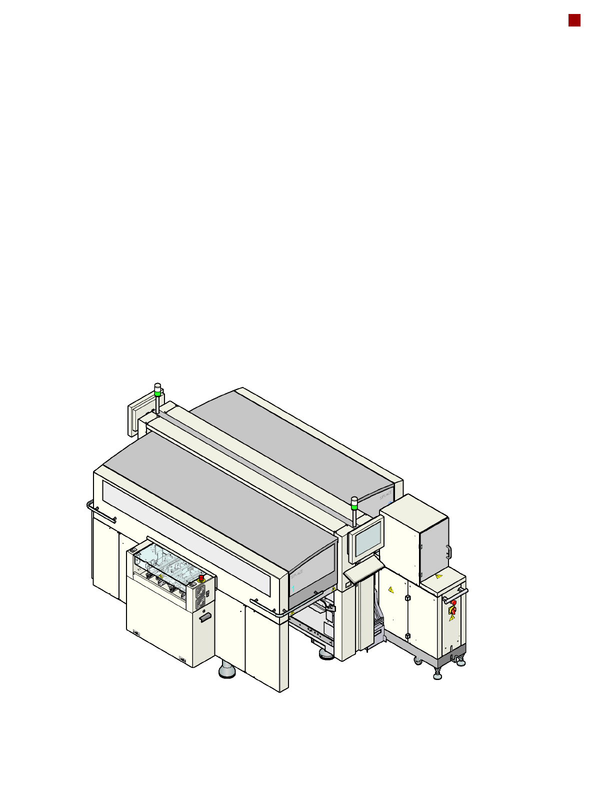
Waffle-Pack Changer (WPC)
The waffle-pack changer
makes the Flatpack IC avail-
able in the waffle-pack trays
to avoid unnecessary loss of
time during storage and
automatic changing of the
waffle-pack trays. Program-
mable, random access to up
to 28 waffle-pack trays also
considerably increases the
range of components that
can be made available. The
waffle-pack changer has an
integral chassis, and is easy
to move to other locations.
It is supplied with the PCB
conveyor height imple-
mented for the machines, but
can also be adapted for the
830, 900, 930 and 950 mm
PCB conveyor heights with
just a few simple operations.
There are 4.5 locations for
30 mm width S feeder mod-
ules available on the compo-
nent table.
Location options
for the WPC:
SIPLACE X3: feeder location 2
SIPLACE X2: feeder locations 2 + 4

34
Component Feeding
Waffle-Pack Changer (WPC)
Technical Data
Electrical ratings
Dimensions (LxW) 1560 x 360 mm²
Height
830 mm ± 15 mm PCB transport height
900 mm ± 15 mm PCB transport height
930 mm ± 15 mm PCB transport height
950 mm ± 15 mm PCB transport height
1360 mm ± 15 mm
1430 mm ± 15 mm
1460 mm ± 15 mm
1480 mm ± 15 mm
Weight approx. 240 kg
Load per unit area 4.19 kN/m²
Dimensions of the waffle-pack tray carrier (L x W x H) 360 x 260 x 6 mm³
Weight of the waffle-pack tray carrier 0.8 kg
Dimensions of the waffle-pack tray including components 341 x 235 x 15 mm³
max. 341 x 235 x 23 mm³
Weight of the waffle-pack tray carrier including the waffle-pack tray and
components max. 1.2 kg
Storage capacity max. 28 waffle-pack tray
carriers
Total weight of the 28 waffle-pack tray carriers 27.6 kg
Weight of the magazine storage unit, waffle-pack tray carriers, waffle-
pack trays and components max. 50 kg
Changeover time for waffle-pack tray carrier
over 1 level
over 10 levels
over 27 levels
1.9 s
2.3 s
2.9 s
Supply voltage 3 x 208 VAC ± 5%; 50/60 Hz (U.S.A.)
3 x 230 VAC ± 5%; 50/60 Hz
3 x 380 VAC ± 5%; 50/60 Hz
3 x 400 VAC ± 5%; 50/60 Hz (European version)
3 x 415 VAC ± 5%; 50/60 Hz
Nominal apparent power 800 VA
Rated current 0.7 A at 3 x 400 VAC
Fuses 3 x 10 or 3 x 16 A

35
Digital Vision System
The digital vision system
guarantees extremely fast
and reliable component rec-
ognition, while being very
simple to use. The system
identifies each individual
component from its shape
and color. Even complex
component shapes, such as
flip-chip or CCGA are
detected extremely reliably.
The system is not only used
in the placement head cam-
eras; it can also be found in
the PCB camera. As well as
ensuring that components
are detected accurately, it
also ensures reliable detec-
tion of the ink spots and PCB
fiducials.
The benefits at a glance:
• Extremely fast and reliable
component detection
• Shortest cycle times
• Robust measurement with
reference to the shape
and color
• Straightforward program-
ming
• Offline programming of
package forms
• Rapid introduction of new
products (NPI)
• Open architecture allows
you to quickly adapt to
new requirements
• Optimum placement
results through individual
measurement of each
component
Digital vision cameras
20-nozzle Collect&Place head camera
12-nozzle Collect&Place head camera
6-nozzle Collect&Place head camera
TwinHead standard and high-resolution camera
2 PCB cameras
Examples of digital vision system analysis times
01005 9 ms
PLC44 17 ms
BGA 225 balls 18 ms