Specification SIPLACE X-Series规格说明书1.pdf - 第8页
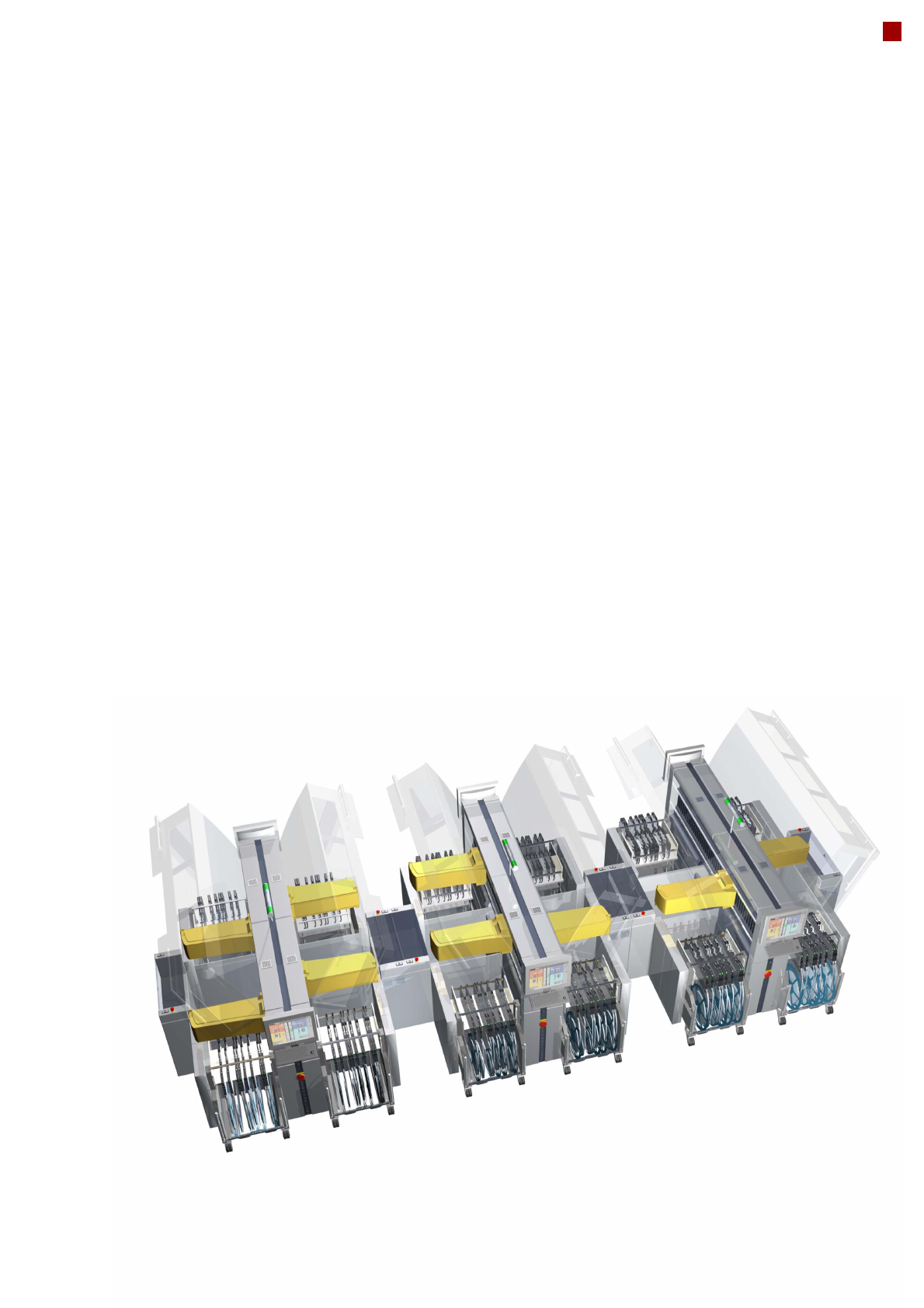
8 Modular Machine Concept Step 1: Placement machine without heads and component changeove r tables SIPLACE X4 SIPLACE X3 SIPLACE X2 Step 2: Selectio n of the placem ent heads 20-nozzle C & P head 12-nozzle C & P …
7
Machine Description
And with respect to the cur-
rent production run, the
SIPLACE vision teaching
station also makes it
extremely simple and fast to
generate package form
descriptions, even for com-
plex components. The set-up
process starts once you have
optimized the product and
defined all the components in
the programming system.
This is also done externally
and then checked by means
of the barcode and data
transfer. This makes the
product change child's play:
the program and all the data
are sent to the line and the
new production run can start.
It just can't get any faster!
Lowest dpm with set-up
verification and sophisti-
cated sensors
The highest machine quality
allows the SIPLACE X-series
to produce the highest prod-
uct quality. This is guaran-
teed by a number of addi-
tional features. Sensors
check the presence and
position of the components
before and after every pick-
up and placement operation
at the placement head, and
the digital vision system
detects the components
faster and more reliably than
the old analog technology. In
addition, set-ups are verified
on the PCB, on the compo-
nent roll and by the intelligent
SIPLACE X feeder modules
with reference to the bar-
code. This network of tests
considerably lowers dpm
rates and increases the first
pass yield.
100% uptime with intelli-
gent feeder modules
The SIPLACE X-series
works with intelligent feeder
modules that greatly simplify
set-up and set-up change
tasks. For example, the
SIPLACE X feeder modules
can even be simply con-
verted while production is
running, thus greatly reduc-
ing machine stoppages.
With all these features, the
SIPLACE X-series is in a
class of its own in SMT pro-
duction, rising far above all
the other placement solu-
tions available on the market.
8
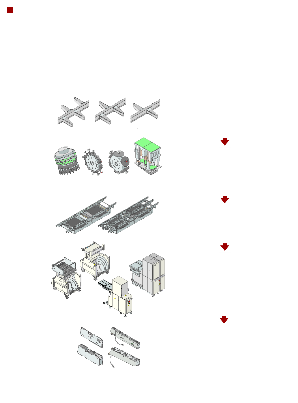
Modular Machine Concept
Step 1: Placement machine without heads and
component changeover tables
SIPLACE X4
SIPLACE X3
SIPLACE X2
Step 2: Selection of the placement heads
20-nozzle C&P head
12-nozzle C&P head
6-nozzle C&P head
TwinHead
Step 3: Selection of the conveyor
Single conveyor
Flexible dual conveyor
Step 4: Selection of the component
changeover tables, MTC, WPC
SIPLACE X component changeover table
SIPLACE HF component changeover table
MTC
WPC
Step 5: Selection of the feeder modules
X tape feeder modules
S tape feeder modules
Label presenter module
Reject conveyor
Linear vibratory feeder
Waffle-pack tray holder
9
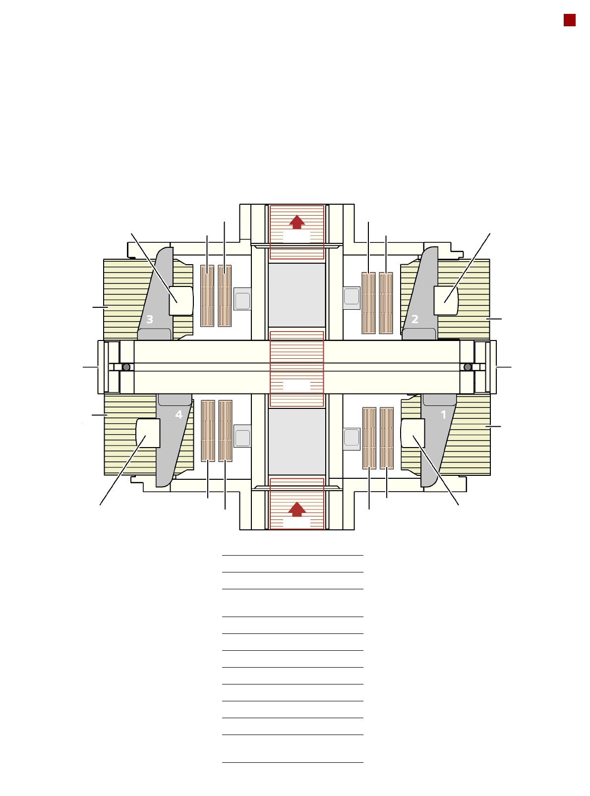
Modular Machine Concept
Example of the SIPLACE X4
NCH2
NCH1
NCH2
NCH1
C&P/TH
X/HF
MTC/X/HF
C&P/TH
NCH2
NCH1
NCH2
NCH1
PA1
PA2
C&P/TH
MTC/X/HF
X/HF
C&P/TH
BZ Buffer zone
C&P Collect&Place head
HF SIPLACE HF compo-
nent changeover table
MTC Matrix Tray Changer
NCH1 Nozzle changer, row 1
NCH2 Nozzle changer, row 2
OP Operator panel
PA1 Placement area 1
PA2 Placement area 2
TH TwinHead
X SIPLACE X component
changeover table
OP
OP
BZ
BZ
BZ