KE2040Instruction Manual Ver2.01,REV04.2003.6.25.pdf - 第11页
viii 14.3.5 Nozzl e outer shaf t ................................................................................ 14-20 14.3.6 ATC brack et ................................................................................…
vii
12.4.5 Setting the Production (Pause) option................................................. 12-14
12.4.6 Setting the Production (Check) option................................................. 12-17
12.4.7 Setting the Use Unit option.................................................................. 12-19
CHAPTER 13 HANDLING THE FEEDERS AND OPTIONS
13.1 Replacement of the Tape Feeder.................................................................... 13-1
13.1.1 Replacement of the tape feeder
(8 mm, 12 mm, 16 mm, 24 mm, and 32 mm) ..................................... 13-1
13.1.2 Replacement of 32-mm adhesive tape feeder .................................... 13-2
13.2 Replacement of the Bulk Feeder..................................................................... 13-3
13.3 Replacement of the Stick Feeder .................................................................... 13-4
13.4 Procedure for Mounting the Matrix Tray Holder on the Feeder Bank.............. 13-5
13.5 Installing the Matrix Tray Changer (MTC)........................................................ 13-6
13.5.1 Installing the Matrix Tray Changer (MTC) ........................................... 13-8
13.6 Handling the Feeder Position Indicator (FPI)................................................... 13-10
13.7 Handling Bad Mark Sensor.............................................................................. 13-11
13.8 Handling HMS.................................................................................................. 13-12
13.9 Replacing Overall feeder exchange trolley...................................................... 13-13
13.10 Handling the IC Collection Belt ........................................................................ 13-15
13.11 Handling a Portable Type Tray Server (DTS).................................................. 13-18
13.12 Handling a Gripper Nozzle............................................................................... 13-19
13.13 Handling the Coplanarity Check Device .......................................................... 13-28
13.13.1 Overview of the coplanarity check device ........................................... 13-28
13.13.2 What to check with this device............................................................ 13-29
13.13.3 Overview of the specifications............................................................. 13-32
13.13.4 Operations........................................................................................... 13-35
13.13.5 Operation options ................................................................................ 13-38
13.12.6 Editing data .......................................................................................... 13-39
13.13.7 Production ........................................................................................... 13-41
13.13.8 Error processing.................................................................................. 13-43
13.13.9 Overview of the coplanarity check operation....................................... 13-44
CHAPTER 14 MAINTENANCE
14.1 Daily Routine Checks....................................................................................... 14-1
14.1.1 List of daily routine checks .................................................................. 14-1
14.2 Check............................................................................................................... 14-3
14.2.1 Air pressure......................................................................................... 14-3
14.2.2 Piping and joint.................................................................................... 14-4
14.2.3 Unit air cylinder.................................................................................... 14-4
14.2.4 Air filter (MNLA Head/FMLA Head) ..................................................... 14-7
14.2.5 Air filter (CAL block)............................................................................. 14-9
14.2.6 Transport belt ...................................................................................... 14-10
14.2.7 Transport pulley................................................................................... 14-11
14.2.8 Notice on Electricity............................................................................. 14-12
14.3 Cleaning........................................................................................................... 14-13
14.3.1 XY axis direct drive unit....................................................................... 14-13
14.3.2 Transport sensors ............................................................................... 14-15
14.3.3 Laser align sensor (MNLA/FMLA head).............................................. 14-16
14.3.4 Nozzle.................................................................................................. 14-18

viii
14.3.5 Nozzle outer shaft................................................................................ 14-20
14.3.6 ATC bracket......................................................................................... 14-22
14.3.7 Feeder bank......................................................................................... 14-23
14.3.8 Z slider shaft ........................................................................................ 14-24
14.3.9 CVS (Component Verification System) (Option).................................. 14-24
14.3.10 Overall feeder exchange trolley (optional) ......................................... 14-25
14.3.11 OCC (Polarizing filter)........................................................................ 14-26
14.3.12 Trackball ............................................................................................ 14-27
14.4 Lubrication........................................................................................................ 14-28
14.4.1 XY-shaft direct drive unit...................................................................... 14-28
14.4.2 Transport screw shaft (Shaft) .............................................................. 14-29
14.4.3 Transport guide shaft........................................................................... 14-29
14.4.4 PWB stopper part ................................................................................ 14-29
14.4.5 Ball screws and Linear way (Head part) .............................................. 14-30
14.4.6 Backup table........................................................................................ 14-31
14.4.7 Movable board transport table ball screw and LM guide ..................... 14-31
14.4.8 Overall feeder exchange trolley (optional)........................................... 14-32
14.5 Replacing the UPS Battery with a New One.................................................... 14-33
14.5.1 Removing the UPS .............................................................................. 14-33
14.5.2 Replacing Batteries.............................................................................. 14-36
14.5.3 Recycling the Used Battery.................................................................. 14-37
14.6 Coplanarity Sensor (Optional).......................................................................... 14-38
14.6.1 Name of each part............................................................................... 14-38
14.6.2 Daily maintenance ............................................................................... 14-38
14.6.3 Parts list............................................................................................... 14-39
DATABASE ........................................................................................................................... 1
ERROR MESSAGES TABLE ........................................................................................ 1
SPECIFICATIONS FOR A CE MACHINE .................................................................. 1
I
Warning
For the safe operation of machinery!!
All personnel engaged in the operation of the chip placer and its accessories (here after
referred to as "machines") including the operators, service and maintenance personnel are
required to read through this safety warning to make familiar with its handling to prevent
accidents and injuries.
This "Warning: For the safe operation of machinery" instructions contain aspects that are
not included in the instruction sheet attached to the product.
The following symbols are used throughout this instructions and on the product for the better
understanding of various warning labels. Please make yourself familiar with the contents
and act accordingly.
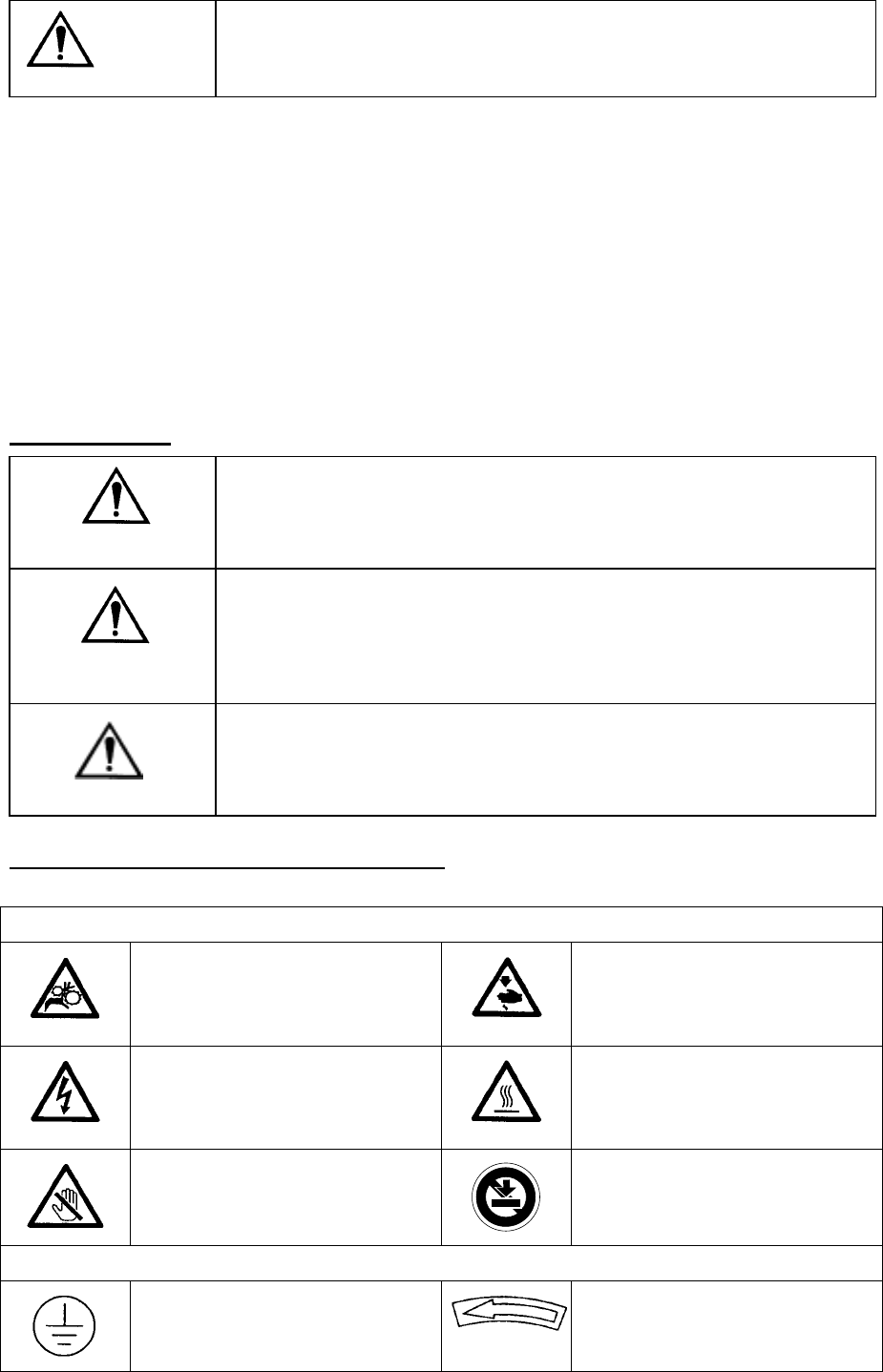
1) Danger levels
Dangerous
Parts of machinery the negligence or mishandling of which
committed during the operation, maintenance or other services on
such parts will lead to severe accidents involving serious personal
injuries or even death.
Warning
Parts of machinery the negligence or mishandling of which
committed, or are left unattended, during the operation,
maintenance or other services on such parts may cause potential
danger to the personnel which may lead to injuries and/or even
death.
Attention
Parts of machinery the negligence or mishandling of which
committed, or are left unattended, during the operation,
maintenance or other services on such parts may cause the
medium-to-light level of hazards to the personnel involved.
2) Warning, prohibition and directive marks
Warning, prohibition and directives are marked with the following symbols:
Warning marks
Your hands or clothes may get
caught by the machines.
Beware of moving parts.
Contacts with them may cause
injuries.
High voltage!!
Beware of electric shocks.
Beware of hot parts.
Contacts with them may cause a
burn.
Beware of movable parts.
Contacts with them may cause
injuries.
If any load is imposed or you
lay your hand on the machine,
it may be damaged.
Directive symbols
It symbolizes a contact to a
grounding wire.
It indicates the direction of turn.