KE2040Instruction Manual Ver2.01,REV04.2003.6.25.pdf - 第420页
5 − 76 5.2.4.6 Operati ng Component View er 5.2.4.6. 1 Opening “Component View er” The “Component Viewer” dialog can be opened f rom t he following 3 screens. ① Vision Form Screen ② Element Data Screen ③ Element Group Sc…
5 − 75
5. Outline-recognized components
- If you define an outline-recognized component with only one type of element
(corner, side or mark) other than a lead and ball, you have to specify two or
more corresponding elements. If you specify another type of element also,
you only have to specify one corresponding element (excluding a side).
- Up to four corners can be specified for this type of component. Note that you
cannot specify two or more corners whose specified angle is the same (theta
offset).
- If another corner or an element (lead, rectangular land or rectangular mark)
having a corner whose angle is the same is located near one corner element,
they should be far from one another by 4 mm or more provided that the
standard VCS is used.
(Since an intersection point outside the outer frame is regarded as a corner
due to the Version 1.10 limitations, two corners (or corner-shaped substance)
should be far from one another by 4 mm or more also.)
- Up to four sides can be specified per component. However, note that two or
more sides whose specified angle is the same (theta offset) cannot be
specified per component. A side should be located on the outer frame, and
its length should be half or longer of the dimension of the component. When
you specify a side (sides) only as an element, include two sides that are
orthogonal
to one
another.
- Up to three marks can be specified per component.
- You can specify a hole as a circle mark of the reverse polarity (dark). In this
case, it has to be displayed as a circle clearly on the screen. (Note that a
hole may not be displayed as a circle clearly on the screen when a thick
component is to be recognized with the perspective light.)
- A mark should be located far from a similar-sized mark or similar-shaped and
similar-sized element (ball or circular land) by 5 mm or more provided that the
standard VCS is used.
6. Notes when a general-purpose vision component data format is used
- Use this format for an element group (especially lead element group) whose
positioning precision is sufficient to be recognized. When you use this format
for an element group (especially lead element group) whose positioning
precision is uncertain, a recognition error may occur frequently.
ー
θ270°Corner
θ0°
Corner2
θ0°
Corner1
θ90°Corner
θ180°Corner
Although there are two corners
whose theta angle is 0 degrees, you
can specify just one corner of them.
<TOP VIEW>
ー
θ270°
Side 1
θ0°
Side 2
θ0°Corner1
θ90°Side
θ180°Side
θ270°
Side 2
Although there are two sides whose
theta angle is 0 degrees and those
whose theta angle is 270 degrees
respectively, you can specify only
either of two sides whose angle is
the same.
<TOP VIEW>
5 − 76
5.2.4.6 Operating Component Viewer
5.2.4.6.1 Opening “Component Viewer”
The “Component Viewer” dialog can be opened from the following 3 screens.
① Vision Form Screen
② Element Data Screen
③ Element Group Screen
The operating method and the contents of data to be displayed on “Component
Viewer” differ depending on the screen from which “Component Viewer” is started.
Table 5.2.4.6-1 Differences in Operating Method and Contents
of Display of “Component Viewer”
Screen from which
“Component Viewer” is
opened
For editing element data Contents of display
Opening from the Vision
Form screen
“Component Viewer” must
be closed.
All element groups are
displayed.
Opening from the Element
Data screen
“Component Viewer” does
not need to be closed.
All element groups are
displayed.
Opening from the Element
Group screen
“Component Viewer” does
not need to be closed.
Only the current element
group is displayed.
5 − 77
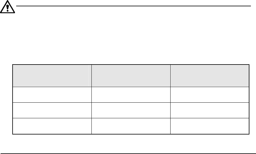
① Opening from the Vision Form screen
When a general vision component is displayed on the Vision Form screen, the
“Component Viewer” button is displayed on the Vision Form screen.
Fig. 5.2.4.6.1-1 [Viewer] Button of Vision Form
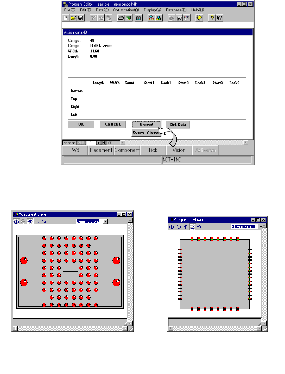
− Clicking the [Component Viewer] button displays the following dialog.
Fig. 6.7.3.6.1-2 Example of
Ball Component Screen Display
Fig. 6.7.3.6.1-3 Example of
Lead Component Screen Display