KE2040Instruction Manual Ver2.01,REV04.2003.6.25.pdf - 第450页
5 − 60 Figure 5.2.4. 4.6 ③ W hen the f irst lead end posit ion is set to (- 20.0 mm, - 5.0 m m), set each v alue in the “First element posit ion” f ield as follows: Off set X : - 20.0 Off set Y : - 5.0 Off set Z: 0 ( not…
5 − 59
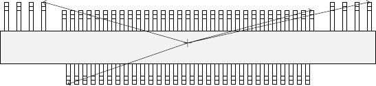
- To be precise, the “First element position” is the distance (offset) from the
center of a component to the first element.
In the same manner as defined for a standard lead components (such as a
QFP, SOP and connector), the first element is the leftmost element when an
element group is located on the bottom side, the lowest element when
located on the right side, the rightmost element when located on the top
side, or the top element when located on the left side. Figure 5.2.4.4.5
shows the first element position of the component used as an example.
For a lead element, the first element position is the end of the first lead with
being viewed from the center of a component.
Figure 5.2.4.4.5
- The direction (angle) of an element group is 0 degrees when it is located on
the bottom side, 90 degrees when located on the right side, 180 degrees
when located on the top side, and 270 degrees when it is located on the left
side with counting anti-clockwise.
In the example, the angle of the first element group is 0 degrees and the
angle of each group from the second element group to fourth element group
is 180 degrees.
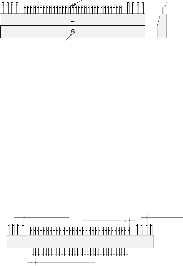
- The VCS finds each element group of a general-purpose vision component,
then recognizes it with assuming that the component center obtained when
you set the element group layout is on the VCS center.
If the component pick-up position is shifted from the center of a component
as shown in Figure 5.2.4.4.6, set the following values as the recognition
offset: an offset for recognizing a component so that the center of a
component can be located on the VCS center.
Recognition offset X: (Xcenter – Xpick)
Y: (Ycenter – Ypick)
When the machine recognizes a general-purpose vision component, the
center for recognizing a component is the component center obtained when
you set the element group layout.
Therefore, if the placement center position of a component is shifted from
the center of a component as shown in Figure 5.2.4.4.6, set the following
values as the Placement offset: an offset for placing a component so that
the placement center point of a component can be moved on the placement
position on a board.
Placement offset X: (Xplace – Xcenter)
Y: (Ycenter – Ycenter)
Top View
Direction: 0 degrees
Direction: 180 degrees
5 − 60
Figure 5.2.4.4.6
③ When the first lead end position is set to (- 20.0 mm, - 5.0 mm), set each value
in the “First element position” field as follows:
Offset X: - 20.0
Offset Y: - 5.0
Offset Z: 0 (not used)
Offset Theta: 0
Set “0” to each field of the setting item “Tolerance”.
* Next, set the element group arrangement.
To set the element group arrangement, the setting items “Dimension”, and
“Count” and “Pitch” of the “Column” and “Row” are provided.
④ Dimension
For a lead element, the dimension is one. Select “1D”.
In the example, the number of leads located in the first element group is 30.
Enter “30” to the “Count” field displayed under the setting item “Row”.
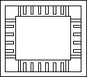
The pitch of each element group is shown in Figure 5.2.4.4.3.
- When the pitch is 0.5 mm, enter “0.5” in the “Pitch” field.
- Set “0” to the “Tolerance” field.
Figure 5.2.4.4.7
⑤ Layout inspection
Set the level used for checking the layout of an element group (checking a
bent lead of a lead component). If you are to check the layout, check the
“Layout inspection” check box. In the same manner as setting of a QFP, use
the ratio of a bent lead to the lead pitch to set the bent lead detection level.
- When you want to set the level to “20 %”, check the “Layout inspection”
check box, then check “20 %”.
Top View
Lead pitch of the first element
group
Lead pitch of the
second element group
Lead pitch of the third element
group
Lead pitch of the fourth
element group
Top View
Component center position (Xcenter, Ycenter)
(component outline center)
Component pick-up position (Xpick, Ypick)
Placement center point of a component
Cross
section
5 − 61
⑥ Missing elements
In the example, there is no missing lead on the element group. If there is/are
a missing element(s), specify this setting item also in the same manner as that
of a QFP.
Up to four blocks of missing leads can be specified per element group.
To specify a block, set the position of the first missing lead and the number of
missing leads located continuously in the same manner when you set those of
a QFP component.
- If three leads are not located from the fifth lead,
Enter “5” to the “Start” field of the “Row” setting item, “3” to the “Count” field.
• Here, you have finished setting an element group. Next, define a recognition
element of this element group.
Only one element can be defined per element group. Even though you define
two or more elements, they are handled as “invalid”.
Click the <Add> button in the “Element” setting field.
1) Element screen
① Type
The lead element types are mainly classified into two: inner leads and outer
leads.
An inner lead refers to a lead whose end faces toward the inside of a
component. An outer lead refers to a lead whose end faces toward the
outside of a component.
- In the example, a component
consists of outer leads.
Select “Outer Lead” from the
“Type” combo box.
Figure 5.2.4.4.8
② Reference pos. (position)
The element origin of a lead element is the lead end as described earlier.
- Select “Center of the bottom” from the “Reference pos.” combo box.
③ Polarity (element polarity)
Specify how bright the image of an element should be.
- Select “Bright” from the “Polarity” combo box because a lead element looks
bright under the reflective light.
④ Offset
Normally, the offset is not used. Set “0” to the “Offset” fields.
Example of
inner leads (of
a socket)