KE2040Instruction Manual Ver2.01,REV04.2003.6.25.pdf - 第425页
5 − 81 Step 1 Component View displ ayed on “Component View er” In the “Com ponent Viewer” dialog, a component is displayed so that all t he element data m ay be included in it. − In t he view that is f irst displayed by …
5 − 80
5.2.4.6.2 How to use “Component Viewer”
− A block diagram of the “Component Viewer” screen is shown below.
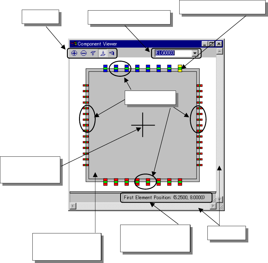
Fig. 5.2.4.6.2-1 Explanation of the “Component Viewer” Screen
Element group selection list
Tool bar
Anchor position (first element)
Cross line
representing the
center of component
Element group
Component shape input
by component data
(including leads)
Coordinates of the first
element of the selected
element group
Scroll bar
5 − 81
Step 1 Component View displayed on “Component Viewer”
In the “Component Viewer” dialog, a component is displayed so that all the
element data may be included in it.
− In the view that is first displayed by clicking the “Component Viewer” button,
the top surface view is displayed if the component is defined by the top
surface or the bottom view is displayed if the component is defined by the
bottom surface.
− The following table shows the relation between the element type and the
default display surface.
Table 5.2.4.6-2 Relation between Default Screen and Component Definition Surface
Element type Default screen display
Outer lead Top surface
Inner lead Bottom surface
Ball Bottom surface
Land Bottom surface
Column Bottom surface
Mark Bottom surface
Side Top surface
Corner Top surface
that when an element defined by the top surface is displayed as a view from
the bottom surface on the “Component Viewer” or when an element defined by
the bottom surface is displayed as a view from the top surface, the element
may be invisible.
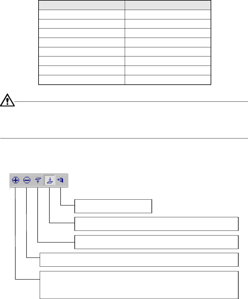
■ Tool bar
End: Closes the V0iewer.
Top View: Displays a view of the component from the top.
Bottom View: Displays a view of the component from the bottom.
Zoom Out: Scales down the component size 10% by clicking the icon.
Zoom In: Displays the icon in the pressed status by clicking the icon.
When you click it with the mouse left-button on the screen, the
component size is scaled up 10%.
5 − 82
Step 2 Selecting an element group
1. Select an element group in the drop-down list displayed on the “Component
Viewer” screen or click an element group that you want to select with the
mouse.
2. After an element group is selected, the selected element group is displayed
in blue and its first element is displayed in yellow. The coordinates of the
first element are displayed in the lower part of the “Component Viewer”
screen.
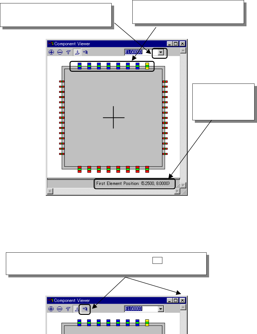
Fig. 5.2.4.6.2-2 Selecting an Element Group
Step 3 Closing the “Component Viewer” screen
Fig. 5.2.4.6.2-3 Closing the “Component Viewer” Dialog
② Or click an element group that you
want to select with the mouse.
The coordinates of
the first element of
the selected element
group are displayed.
① When you click this position, a list of
element groups is displayed.
When you click the “Close” button of the tool bar or the [ X ] button in the
upper right part of the dialog, the “Component Viewer” screen can be closed.