KE2040Instruction Manual Ver2.01,REV04.2003.6.25.pdf - 第427页
5 − 83 5.2.4.6. 3 Editi ng data Step 1 W hen “Component Viewer” is displayed f rom the Elem ent Data scr een, the Element Gr oup screen can be opened without closing the “ Component Viewer” screen. Fig. 5.2. 4.6.3-1 Open…
5 − 82
Step 2 Selecting an element group
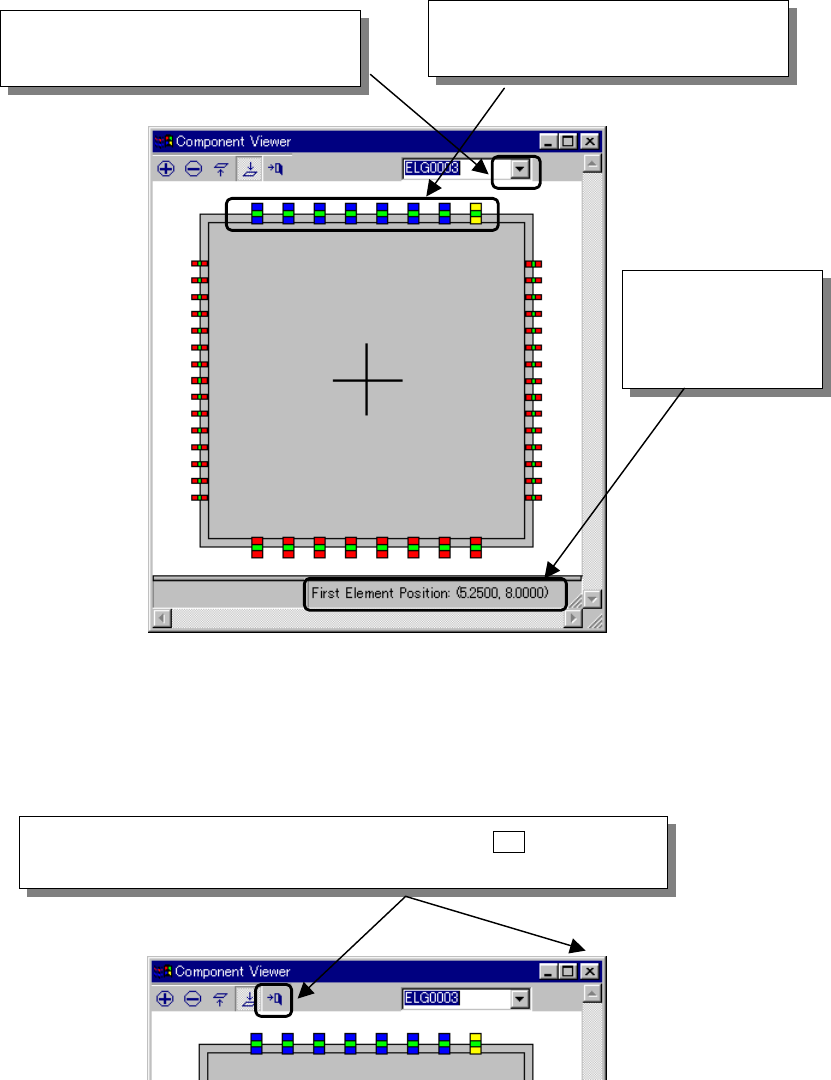
1. Select an element group in the drop-down list displayed on the “Component
Viewer” screen or click an element group that you want to select with the
mouse.
2. After an element group is selected, the selected element group is displayed
in blue and its first element is displayed in yellow. The coordinates of the
first element are displayed in the lower part of the “Component Viewer”
screen.
Fig. 5.2.4.6.2-2 Selecting an Element Group
Step 3 Closing the “Component Viewer” screen
Fig. 5.2.4.6.2-3 Closing the “Component Viewer” Dialog
② Or click an element group that you
want to select with the mouse.
The coordinates of
the first element of
the selected element
group are displayed.
① When you click this position, a list of
element groups is displayed.
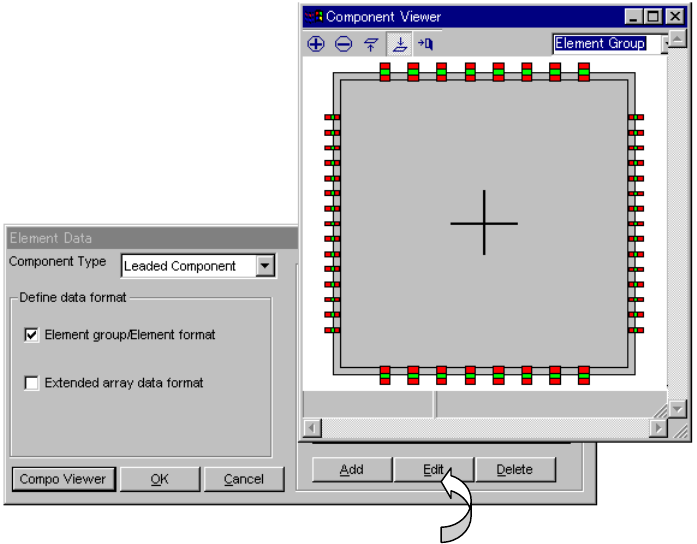
When you click the “Close” button of the tool bar or the [ X ] button in the
upper right part of the dialog, the “Component Viewer” screen can be closed.
5 − 83
5.2.4.6.3 Editing data
Step 1
When “Component Viewer” is displayed from the Element Data screen, the
Element Group screen can be opened without closing the “Component
Viewer” screen.
Fig. 5.2.4.6.3-1 Opening the Element Group Screen
− When you click the <Edit> button, the data displayed on the “Element Group”
screen can be edited.
5 − 84
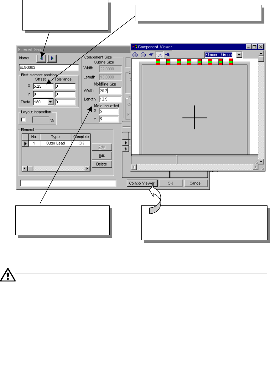
Step 2
When “Component Viewer” is displayed from the Element Group screen, data
can be edited on the Element Group screen or the Element Data Editing
screen can be opened without closing the “Component Viewer” screen.
Fig. 5.2.4.6.3-2 Editing Data on the Element Group Screen
■
Mold field
The external dimensions of a lead component include a lead length.
Accordingly, if the lead component is displayed on the basis of the external
dimensions, it is displayed as if the lead were in the mold portion. When you
input the mold length and the mold line offset value, the lead component can
be accurately displayed.
−
Input both mold length and mold line offset value in the Element Group screen.
−
This function is an optional input item for view. If you do not input this item,
the external dimensions of the component are displayed.
Step 3
After editing data, click the “Component Viewer” button, and the edited
contents are reflected in “Component Viewer”.
When you click this arrow, the
previous or next element
group data can be displayed.
Element group data or element data is edited.
When you click the [Component Viewer]
button after editing data, the edited contents
are reflected in
“
Component Viewer
”
.
Mold field
[Refer to the following.]