KE2040Instruction Manual Ver2.01,REV04.2003.6.25.pdf - 第408页
5 − 45 ⑲ Exp (Expansion) Set this item f or an extended- lead connector , or unidirectional connect or . - W hen you click t his item with the rig ht butt on, the select ion pop-up menu appears on the screen. ▼ W hen you…
5 − 44
2) Number of leads to be recognized
Enter the number of leads at each corner to be recognized. See the
conditions for entering the number of leads shown in Table 5.2.3.16 below.
Table 5.2.3.16.1 Range of the number of leads
Range of the number of leads
Component type Recognition pattern
Upper
left
corner
Upper
right
corner
Lower
left
corner
Lower
right
corner
Unidirectional
connector
All
Only the both ends lead
Both ends lead exclusion
****
1-3
0-3
****
1-3
0-3
****
****
****
****
****
****
Bidirectional
connector
Z-shaped lead
connector
All
Only the both ends lead
Both ends lead exclusion
****
1-3
0-3
****
1-3
0-3
****
1-3
0-3
****
1-3
0-3
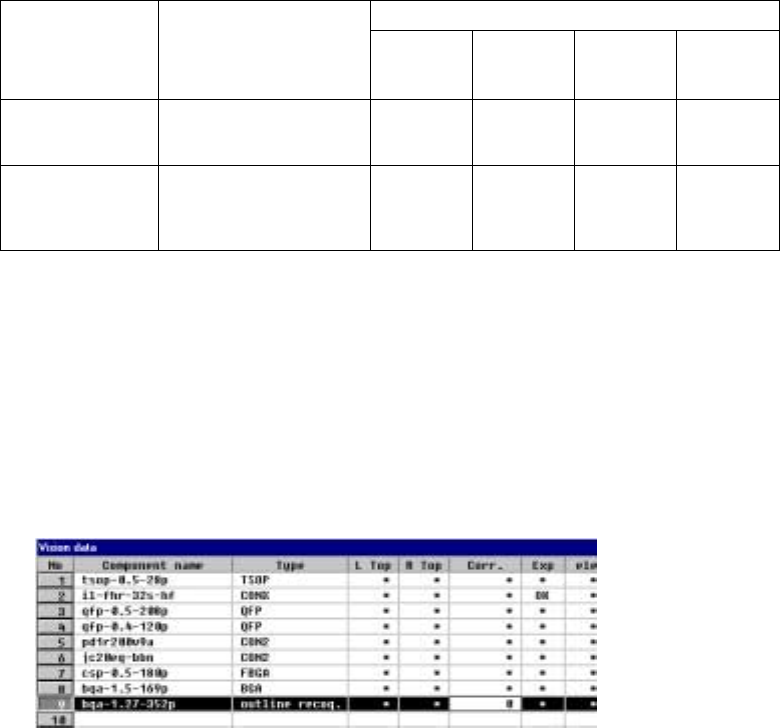
⑱ Corr.(Brightness correction)
Set the threshold to be applied when the machine recognizes an
outline-recognized component.
- “0” is set as the initial value. If the machine cannot recognize such a
component, adjust the initial value between – 127 and + 127. When a
component looks darker, set the smaller number. When you can see even
the background of a component, increase the value.
5 − 45
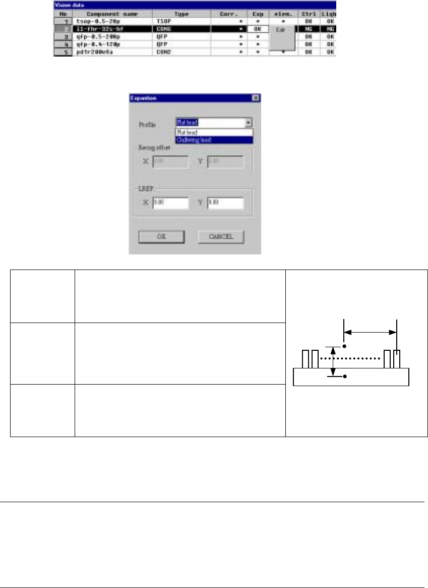
⑲ Exp (Expansion)
Set this item for an extended-lead connector, or unidirectional connector.
- When you click this item with the right button, the selection pop-up menu
appears on the screen.
▼ When you click the [Edit] command, the following screen appears.
Profile Set the shape of a lead.
- Flat lead
- Gullwing lead
By default, “Gullwing lead” is selected.
Recog offset
(Recognition
offset)
Displays the recognition center offset which was set on
the “Expansion” window invoked from the Component
data screen. You cannot edit any of these values on
this screen. This item shows the coordinates of the
lead center A with being viewed from the component
pick-up position C.
LREP.
(Rightmost
lead position)
Enter the coordinates of the rightmost lead position:
coordinates of the rightmost lead center B with being
viewed from the lead center A. The default value is
determined based on the lead pitch and number of
leads.
♦ When you finish entering all of data, click the <OK> button. The “Vision
data” screen reappears.
Notes:
①
The machine cannot recognize images of an extended-lead connector with
dividing it.
②
Note that only one point, the rightmost lead position is set on this screen, so
the recognition precision is insufficient.
C
CC
C
A
AA
A
B
BB
B
5 − 65
5.2.4.4.2 Ball components (Element group/Element format)
− This section describes the procedure for creating data on ball components
(complex array components).
1. Operation on the “Extended Vision” screen
- Select “Ball Component” from the “Component Type” combo box.
- Check the “Element group/Element format” check box in the “Define data
format” field.
- Click the <Add> button on the “Element Group List”.
2. Operation on the “Element Group” screen
Define an element group.
An element group consists of components whose size and pitch is the same as
each other.
A complex array component refers to an area array component whose size is
different or whose ball/land pitch is different from each other.
When the lead pitch is not the same even though the polarity is the same, set
element groups separately. If the polarity is the same, the size and shape of the
polarity is the same also.
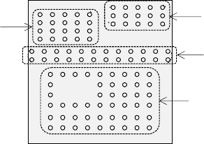
In the example shown in Figure 5.2.4.4.11, a complex array component that
consists of four element groups is shown.
• The procedure for creating data on this component is to be described below.
The element size and pitch of the second and third element groups are the
same as each another. However, columns of elements are not aligned with
each another. Define them as two different element groups.
The posture of a complex array component is viewed from the bottom in the
same manner as an area array component such as a BGA and FBGA.
Figure 5.2.4.4.11
Bottom View
Third element group
Fourth element group
Second element group
First element group