KE2040Instruction Manual Ver2.01,REV04.2003.6.25.pdf - 第433页
5 − 89 Item Descripti on VCS Selection Select a VCS used for rec ognizing a c omponent : Standard (50 m m) 37.5 m m opti on VCS 27 mm option V CS 18 mm option V CS VCS Focus Height Specify t he height the V CS recognizes…
5 − 88
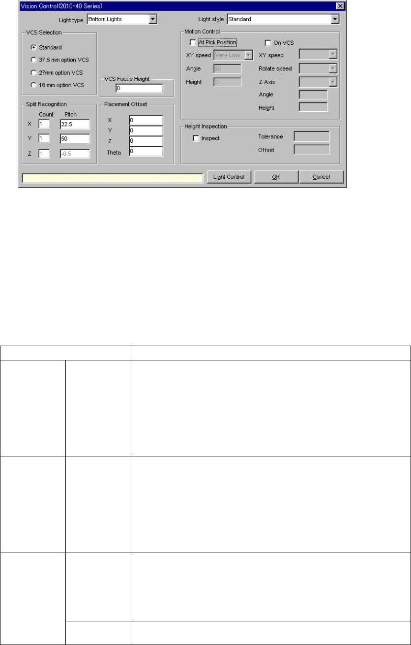
5.2.5 Ctrl (Control)
When you click the [Edit] command displayed in the “Ctrl” field, the following screen
appears.
• Set the light used for recognizing divided image in the following order:
1. Set a VCS used for recognizing a component.
2. Determine the division recognition.
3. Specify the Light type and Light style (when the Light type is “Back lights” or
“Side lights”).
4. Set the other items.
• Detailed description of each setting item
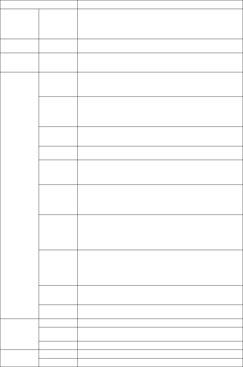
Item Description
Light type Select the light type:
- Bottom Lights
This type of light is a red light consisting of three light blocks: coaxial light
(half mirror light), bottom light and red side light (upper and lower stages).
- Back Lights
This type of light is a green light used for using the shade of a component
to center the component that cannot be illuminated with the back light.
- Side Lights
This is a light (normally blue light) used for recognizing a solder ball of a
BGA (FBGA).
Light style Select the sub light type.
Bottom
- Standard
- CBGA
- LGA
Side
- Red side light
- Red side light equipped with a pop-up light
- Blue side light
- Blue side light equipped with a pop-up light
Count Set the number of divisions of image in the X, Y and Z directions.
The number of divisions in each direction is:
X: 1 to 2
Y: 1 to 3
Z: 1 to 2
(See Section 5.2.5.1 “Applicable component dimensions during division
recognition”.)
Split
recognition
Pitch Specify the distance over which a VCS moves. The value range varies
depending on the selected VCS.
5 − 89
Item Description
VCS
Selection
Select a VCS used for recognizing a component:
Standard (50 mm)
37.5 mm option VCS
27 mm option VCS
18 mm option VCS
VCS Focus
Height
Specify the height the VCS recognizes.
(Distance from the component bottom to the lead bottom side)
Placement
Offset
X, Y, Z, θ
Enter an offset for each component which is used for placement. Note that
this offset functions in the same manner the recognition offset of
Component data does.
At Pick
Position
Check this check box when you set the posture of a component at the
pick-up position.
(The machine checks the posture of a component when it picks up the
component, then moves it onto the VCS.)
XY speed Select the speed for controlling the posture of a component:
- Very Slow (default)
- Slow
- Medium
- High
Angle Enter the angle of the component posture after it is picked up.
Allowable input range: 0 to 359 degrees (default: 90 degrees)
This angle is automatically and optimally controlled.
Height Enter the height when a component is being rotated.
Allowable input range: - 20.0 mm to 20.0 mm (default: 0 mm)
On VCS Check this check box when you want to set the component posture control
on the VCS.
(This item is available only for a large component.) (When the machine
recognizes divided images of a component)
XY speed Select the speed for recognizing divided images of a component:
- Very Slow
- Slow
- Medium
- High
Rotate speed Select the rotation speed when the machine recognizes divided images of a
component:
- Very Slow
- Slow
- Medium
- High
Z Axis Select the speed of the Z axis when the machine recognizes divided
images of a component:
- Very Slow
- Slow
- Medium
- High
Angle Enter the posture of a component when the machine recognizes it.
Allowable input range: 90 degrees
The angle is automatically and optimally controlled.
Motion
Control
Height Enter the height of a component when it is being rotated (Not used).
Allowable input range: - 20.0 mm to 20.0 mm
Yes Check this check box to check the height.
Tolerance Enter the error range of the coplanarity check.
(Default: 0.2 mm)
Height Level
Offset Enter the offset value of the coplanarity check. (Default: 0.25 mm)
OK Sets the data.
Cancel Cancels the data setting.
5 − 90
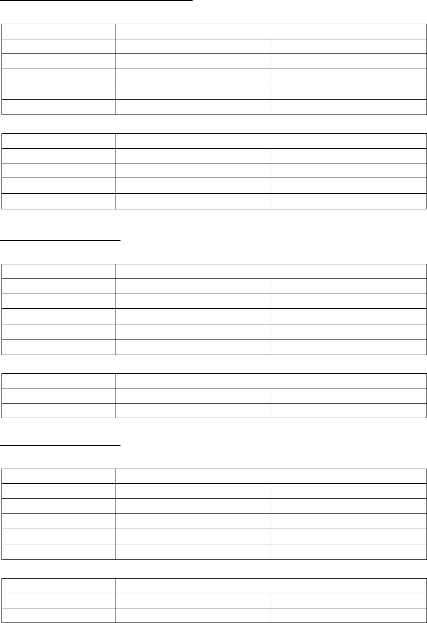
5.2.5.1 Applicable component dimensions during division recognition
Standard VCS (54.00 mm x 54.00 mm)
- Bottom (reflective) light
Dimensions of applicable components
Division mode Longer side Shorter side
Standard 50.00 – 3.00 mm 50.00 – 3.00 mm
1 × 2
100.00 – 50.01 mm 3.00 – 50.00 mm
1 × 3
150.00 – 100.01 mm 3.00 – 50.00 mm
2 × 2
75.00 – 50.01 mm 75.00 mm – 50.01 mm
- Back (penetrative) light
Dimensions of applicable components
Division mode Longer side Shorter side
Standard 50.00 – 9.00 mm 35.00 – 9.00 mm
1 × 2
100.00 – 50.01 mm 35.00 – 17.00 mm
1 × 3
120.00 – 100.01 mm 35.00 – 17.00 mm
Optional 37.00 mm-VCS
- Bottom (reflective) light
Dimensions of applicable components
Division mode Longer side Shorter side
Standard 34.00 – 3.00 mm 34.00 – 3.00 mm
1 × 2
68.00 – 34.01 mm 34.00 – 3.00 mm
1 × 3
102.00 – 68.01 mm 34.00 – 3.00 mm
2 × 2
68.00 – 34.01 mm 68.00 mm – 34.01 mm
- Back (penetrative) light
Dimensions of applicable components
Division mode Longer side Shorter side
Standard 34.00 – 9.00 mm 34.00 – 9.00 mm
Optional 27.00-mm VCS
- Bottom (reflective) light
Dimensions of applicable components
Division mode Longer side Shorter side
Standard 24.00 – 3.00 mm 24.00 – 3.00 mm
1 × 2
48.00 – 24.01 mm 24.00 – 3.00 mm
1 × 3
72.00 – 48.01 mm 24.00 – 3.00 mm
2 × 2
48.00 – 24.01 mm 48.00 mm – 24.01 mm
- Back (penetrative) light
Dimensions of applicable components
Division mode Longer side Shorter side
Standard 24.00 – 9.00 mm 24.00 – 9.00 mm