KE2040Instruction Manual Ver2.01,REV04.2003.6.25.pdf - 第870页
13 − 30 − − − − Coplanarity of a lead component in t he three-point method (reg ulated by EIAJ: default) In the g eometric plane passing the bott om points of optional t hree term inals, all the bottom points of the othe…
13 − 29
13.13.2 What to check with this device
13.13.2.1 Colinearity check
The colinearity check inspects how much a side on which leads are located is bent in
the up/down directions.
− This check is performed with scanning a component with laser only once.
For example, for a component having four sides such as a QFP, the device scans
each of four sides with single scanning, and for a component having two sides
such as an SOP, the device scans each of two sides with single scanning.
Figure 13.13.2.1 Explanation of component check
“Colinearity” means parallelness. The machine can perform a colinearity
check for a lead component only.
13.13.2.2 Coplanarity check
Two methods are provided to obtain a coplanarity value:
Method regulated by EIAJ: appropriate for a QFP component.
Least squares method (by obtaining evenness of the terminal lowest side)
− At the factory, this device is set to obtain a coplanarity value with the method
regulated by EIAJ. (You can change this setting on the Machine setup menu.)
− This device checks a QFP component with EIAJED-7401-4, and an SOP
component with EIAJED-7304-1 or the least squared method.
− This device checks a ball component with EIAJED-7304.
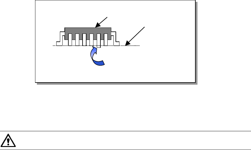
− The method regulated by EIAJ regards a distance from the virtual plane to the
lowest point of the farthest terminal in the vertical direction of all terminals as a
coplanarity value.
Component to be checked
Line for measurement
Lead bent downward
13 − 30
−
−−
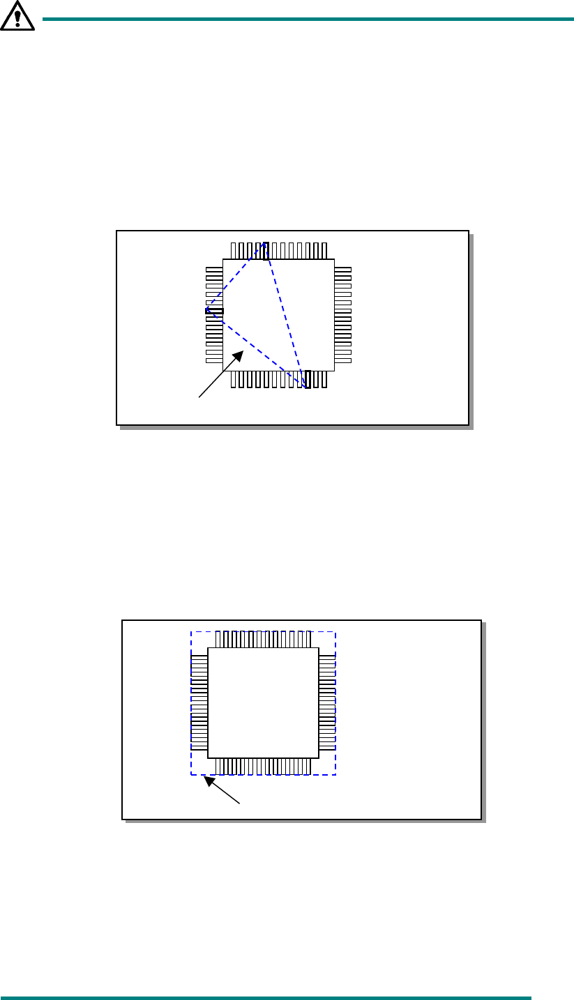
− Coplanarity of a lead component in the three-point method
(regulated by EIAJ: default)
In the geometric plane passing the bottom points of optional three terminals,
all the bottom points of the other terminals exist on the package side and the
center of gravity of the package is included within or on the triangle
comprised of these three points. When the plane satisfies the above
condition and has no effect of the empty weight, it is defined as coplanarity.
In case there are multiple combinations that satisfy the above condition,
adopt a combination in which the coplanarity value becomes large.
Fig. 13.13.2.2 Calculation of Coplanarity by in the three -point method
−
−−
− Coplanarity of a lead component in the method of least squares
In the method of least squares, when the plane obtained by the method of
least squares from the bottom points of all the terminals is in contact with the
bottom point of the most distant terminal from the package side, the distance
up to the most distant terminal is defined as coplanarity.
Fig. 13
Fig. 13.13.2.3 Calculation of Coplanarity by the Method of Least Squares
−
−−
− Coplanarity of a ball component in the method of least squares
(regulated by EIAJ)
When the plane obtained by the method of least squares from the vertexes of all
balls is in contact with the vertex of the most distant ball from the package side,
the distance up to the most distant ball is defined as coplanarity.
Plane obtained by the lowest points
Plane obtained by the method
of least squares
13 − 31
13.13.2.3 Evaluation criteria
−
−−
− Colinearity check (Applicable to a lead component only)
The device checks how much leads on each side are bent in the up/down
direction based on the value that is entered to the menu item “Tolerance”
displayed on the “COPLA CHECK DATA” dialog box invoked from the Vision data
screen.
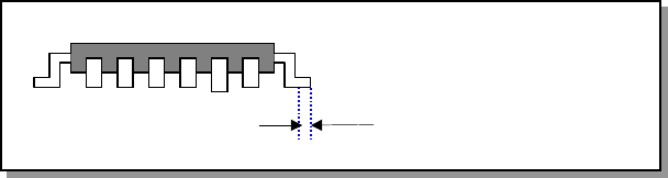
− The position to be checked can be set with the menu item “Scanning Offset” on
the Vision data editing screen.
Figure 13.13.2.4 Explanation of the scanning position offset
−
−−
− Coplanarity check
The device checks how much a lead is bent in the up/down directions based on
the value that is entered to the menu item “Tolerance” displayed on the “COPLA
CHECK DATA” dialog box invoked from the Vision data screen.
Scanning position offset