KE2040Instruction Manual Ver2.01,REV04.2003.6.25.pdf - 第856页
13 − 16 This unit allows the machine t o collect components which are not placed on a boar d for some reason without damag ing them aft er the component s are recog nized with the VCS. Components which are placed on the …
13 − 15
13.10 Handling the IC Collection Belt
1. Specifications
(1) Applicable components
Component type: QFP, SOP, PLCC and so on
(components recognized with the VCS)
Component size: 10 mm x 10 mm to 50 mm x 50 mm, 1.0 mm to 6.0 mm
(2) Number of ICs to be collected
5 to 19 (this number varies depending on the size of an IC)
(3) How much the belt is to be fed
15 mm to 55 mm (in increments of 5 mm): manually set the rotary switch
according to the size of an IC to be collected.
(4) Belt
Anti-static belt: width 5 mm
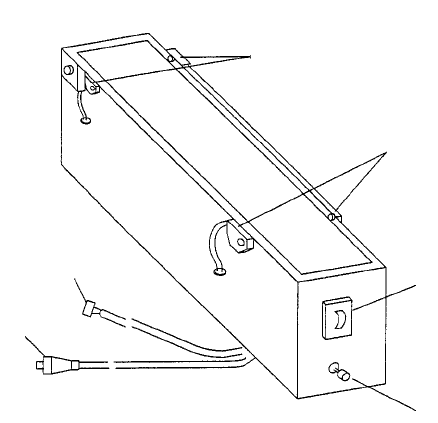
2. Configuration and parts identification of the IC collection belt
Figure 13.10.1 Parts identification of the IC collection belt
① Component sensor
② Stop sensor
③ IC size setting rotary switch
④ Reset switch
⑤ Power plug
⑥ ALARM signal connector
①
②
③
④
⑤
⑥
13 − 16
This unit allows the machine to collect components which are not placed on a board for
some reason without damaging them after the components are recognized with the
VCS.
Components which are placed on the component sensor ① from the head are fed
sequentially at the pitch selected with the rotary switch ③.
When the belt is full of components and the Stop sensor ② detects a component, the
main unit pauses and displays the message on the screen.
CAUTION
To avoid a risk of injury and prevent the machine from being damaged,
be sure to collect components only after detaching the IC collection belt
from the feeder bank or after you check to see if the machine stops
completely.
If you are to collect components from the IC collection belt being fixed
on the feeder bank, be sure to check to see if there is no person who
may start the machine unexpectedly.
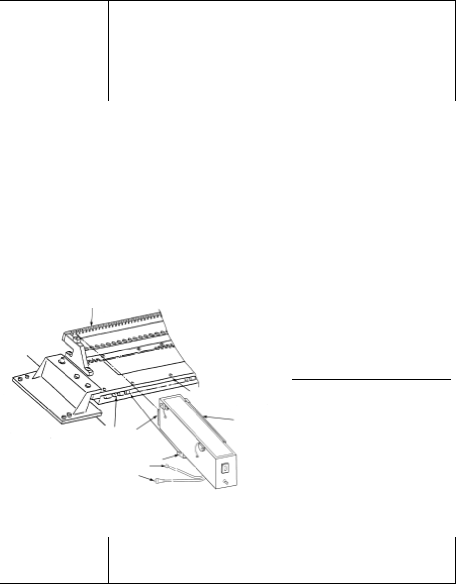
3 Attaching and detaching the IC collection belt
(1) Place the bottom of the IC collection belt ① on the feeder bank ②.
(2) Slide the IC collection belt to align the front positioning pin ⑤ of the IC collection
belt with the fixing hole of the fixing plate ③. Align the lock holder ⑦ with the
V-shaped groove of the lock shaft ⑥, then push the lock holder until it becomes
in contact with the fixing plate ③. Connect the power plug ⑧ of the IC
collection belt to the jack ⑨ of the main unit, and the ALARM signal connector
⑩ to the relay cable.
Note: Check to see if the IC collection does not float nor be tilted.
(3) To detach the IC collection belt,
pull the IC collection belt ①
toward the rear while pulling the
lever of the lock holder ⑦ to
detach it.
Figure 13.10.2 Attaching/detaching the IC collection belt
CAUTION
To avoid any accident caused by sudden activation of the machine,
turn off the power.
Note: Attach or detach the IC
collection belt on/from
the main unit only after
the machine stops
because it is very
dangerous to attach or
detach it in Production
mode or while the X-Y
axes are moving.
①
③
②
⑥
⑤
⑦
⑩
⑧
13 − 17
4. Operation
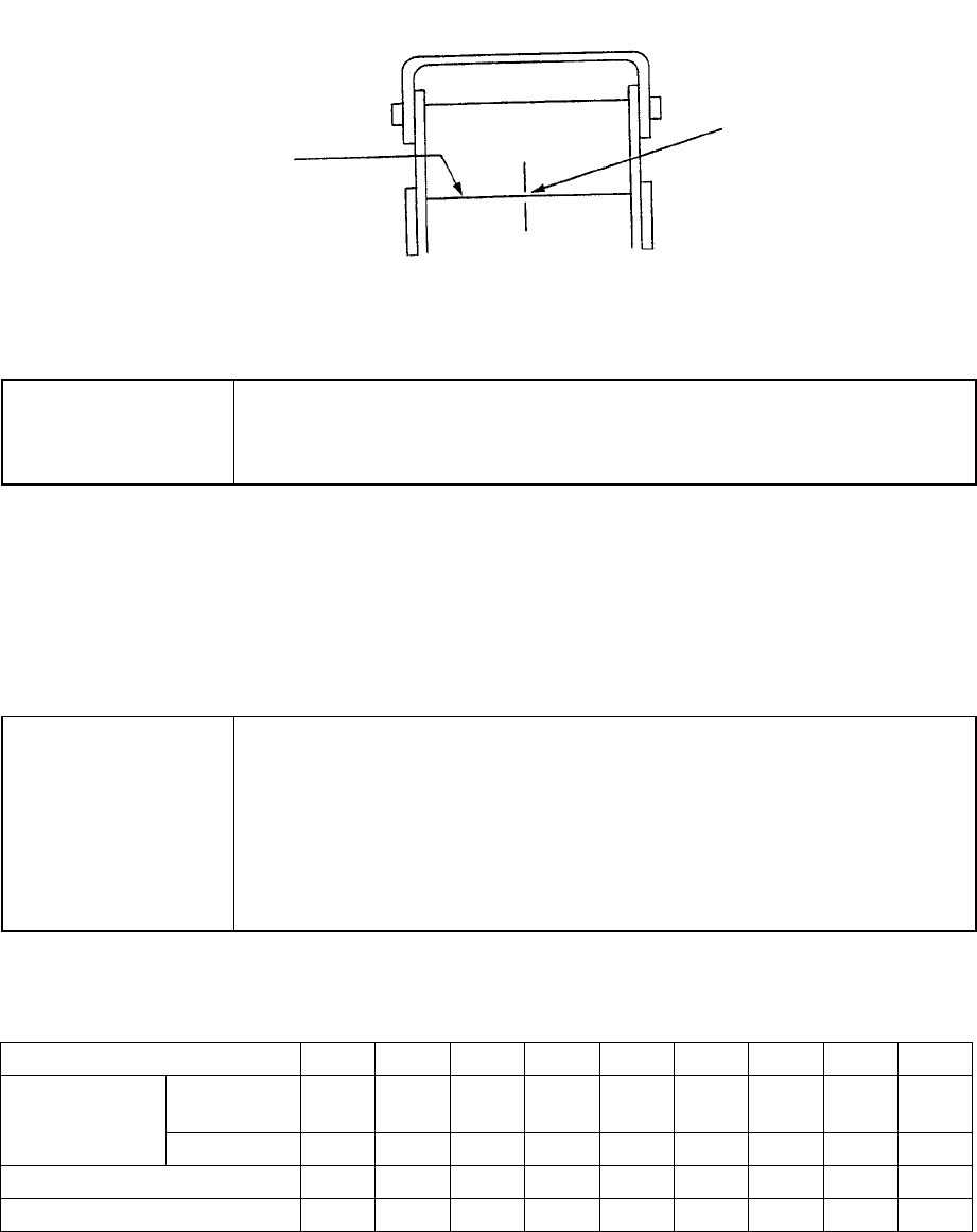
(1) Teaching
Fix the IC collection belt on the feeder bank, and teach the coordinates of the IC
collection belt position which is selected on the Machine setup menu.
Teaching position
Figure 13.10.3 Teaching operation
CAUTION
To avoid a risk of injury, do not place your hand in the machine, nor
move your face or head close to the machine during operation of the
HOD.
(2) Basic operation
The head of the main unit places an IC on the belt, and the component sensor
detects it. After 0.5 seconds, the IC is fed over the belt at the pitch you set. If
the belt gets full of ICs and stops, press the Reset switch to restart the machine
after removing ICs from the belt.
CAUTION
To avoid a risk of injury and prevent the machine from being damaged,
be sure to collect components only after detaching the IC collection belt
from the feeder bank or after you check to see if the machine stops
completely.
If you are to collect components from the IC collection belt being fixed
on the feeder bank, be sure to check to see if there is no person who
may start the machine unexpectedly.
Table 13.10.1 Number of ICs which can be collected
and the feeding pitch set with the rotary switch No.
Switch No. to be set 1 2 3 4 5 6 7 8 9
Equal or
less than
10 15 20 25 30 35 40 45 50 IC size (mm)
Over − 10 15 20 25 30 35 40 45
Belt feeding pitch (mm) 15 20 25 30 35 40 45 50 55
Maximum number of ICs 19 14 11 9 8 7 6 6 5
Optical axis
Teach the center of the
belt on the component
sensor optical axis.