KE2040Instruction Manual Ver2.01,REV04.2003.6.25.pdf - 第454页
5 − 64 Element group name First element position Layout inspection (Dimension) Missing elements Element Element offset Element size Element shape Cutting Lead size ELG0001 X:-7.25 Y : -5.1 Z: 0 θ : 0 To l e r a n c e : A…
5 − 63
⑪ Lead size
For a gullwing lead, enter the lead foot size here.
The “lead foot size” indicates the portion of a gullwing lead which is in contact
with a board.
- In the example, the length of a gullwing lead foot is 0.5 mm.
Enter the following values:
Width: 0.2 (same as the lead width)
Length: 0.4
♦ - Here, you have finished entering element data. When you click the <OK>
button displayed on the lower right corner, the “Element Group” screen
reappears.
- You have finished defining the first element group. When you click the
<OK> button displayed on the lower right corner, the “Extended Vision”
screen reappears.
• When you have the next element group to be defined at this point, click the <Add>
button to define the element group by entering data in the same manner.
In the example, there are four element groups. Define four element groups.
All data to be entered is shown below:
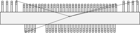
Figure 5.2.4.4.10
Top View
Forth element group
(X, Y): (- 9.50, 5.1) mm
Theta: 180 degrees
Pitch: 0.5 mm, Count: 4
Lead length: 1.2 mm
Lead width: 0.4 mm
Gullwing lead: Flat
Foot length: 0.6 mm
Foot width: 0.4 mm
Third element group
(X, Y): (7.5, 4.9) mm
Theta: 180 degrees
Pitch: 0.5 mm, Count: 31
Lead length: 1.0 mm
Lead width: 0.2 mm
Gullwing lead: Flat
Foot length: 0.4 mm
Foot width: 0.2 mm
Second element group
(X, Y): (13.31, 5.1) mm
Theta: 180 degrees
Pitch: 1.27 mm, Count: 4
Lead length: 1.2 mm
Lead width: 0.4 mm
Gullwing lead: Flat
Foot length: 0.6 mm
First element group
(X, Y): (- 7.25, - 5.1) mm
Theta: 0 degrees
Pitch: 0.5 mm, Count: 30
Missing leads: three from the
fifth lead
Lead length: 1.0 mm
Lead width: 0.2 mm
Gullwing lead: Flat
Foot length: 0.4 mm
Foot width: 0.2 mm
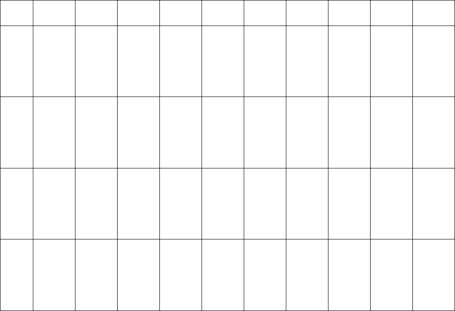
5 − 64
Element
group
name
First
element
position
Layout
inspection
(Dimension)
Missing
elements
Element
Element
offset
Element
size
Element
shape
Cutting Lead size
ELG0001 X:-7.25
Y: -5.1
Z: 0
θ: 0
Tol er an ce :
All set to 0.
√ 25% √ ID
Count of
Column: 30
Pitch of
Column:
0.5
Tolerance:
0
Start: 5
Count: 3
Type: Outer
Lead
Reference
pos.:
Center of the
bottom
Polarity:
Bright
Offset: all
set to 0.
Tolerance:
all set to 0.
Size
X: 0.2
Y: 1.0
Tolerance:
all set to 0.
Profile:
Gullwing
Cut shape:
Flat
Coating:
Bare
Cut width:
0
Cut length:
0
Size
X: 0.2
Y: 0.4
Tolerance:
all set to 0.
ELG0002 X: 13.31
Y: 5.1
Z: 0
θ: 180
Tol er an ce :
All set to 0.
√ 25% √ ID
Count of
Column: 4
Pitch of
Column:
1.27
Tolerance:
0
Type: Outer
Lead
Reference
pos.:
Center of the
bottom
Polarity:
Bright
Offset: all
set to 0.
Tolerance:
all set to 0.
Size
X: 0.4
Y: 1.2
Tolerance:
all set to 0.
Profile:
Gullwing
Cut shape:
Flat
Coating:
Bare
Cut width:
0
Cut length:
0
Size
X: 0.4
Y: 0.6
Tolerance:
all set to 0.
ELG0003 X: 7.5
Y: 4.9
Z: 0
θ: 180
Tol er an ce :
All set to 0.
√ 25% √ ID
Count of
Column: 31
Pitch of
Column:
0.5
Tolerance:
0
Type: Outer
Lead
Reference
pos.:
Center of the
bottom
Polarity:
Bright
Offset: all
set to 0.
Tolerance:
all set to 0.
Size
X: 0.2
Y: 1.0
Tolerance:
all set to 0.
Profile:
Gullwing
Cut shape:
Flat
Coating:
Bare
Cut width:
0
Cut length:
0
Size
X: 0.2
Y: 0.4
Tolerance:
all set to 0.
ELG0004 X: -9.5
Y: 5.1
Z: 0
θ: 180
Tol er an ce :
All set to 0.
√ 25% √ ID
Count of
Column: 4
Pitch of
Column:
1.27
Tolerance:
0
Type: Outer
Lead
Reference
pos.:
Center of the
bottom
Polarity:
Bright
Offset: all
set to 0.
Tolerance:
all set to 0.
Size
X: 0.4
Y: 1.2
Tolerance:
all set to 0.
Profile:
Gullwing
Cut shape:
Flat
Coating:
Bare
Cut width:
0
Cut length:
0
Size
X: 0.4
Y: 0.6
Tolerance:
all set to 0.
Click the <OK> button at the lower left corner of the screen after you define all element groups to finish the “Extended Vision”
data entry.
5 − 92
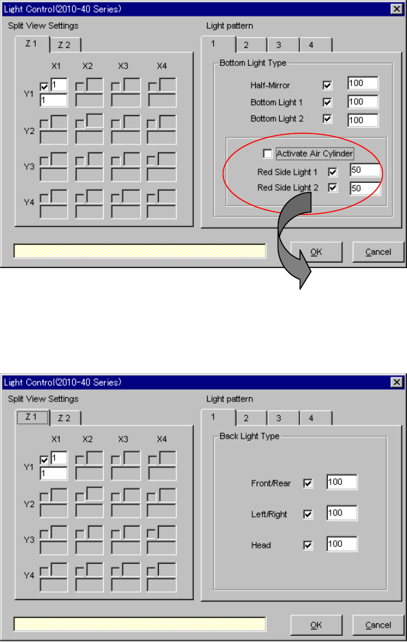
5.2.6 Light
To change the light data, use the “Light Control” data-editing screen shown in Section
5.2.5 “Ctrl”.
- Split view settings on the “Light Control” screen: The available setting items vary
depending on the value set in the “Split Recognition” fields displayed on the
“Vision Control” screen.
- Light pattern on the “Light Control” screen: The available setting items vary
depending on selection of the “Light type” and "Light style" on the “Vision Control”
screen.
▼ When “Bottom Lights” is selected from the “Light Type” combo box and
“Standard” is selected as the "Light style"
▼ When “Back Lights” is selected from the “Light Type” combo box
* When you select “CBGA” or “LGA” in
the “Light Style” field, the check
boxes “Red Side Light 1” and “Red
Side Light 2” are not checked.