KE2040Instruction Manual Ver2.01,REV04.2003.6.25.pdf - 第411页
5 − 67 Bottom View 13 24 5 1234 56 ▼ To be precise, the “First element posit ion” is the distance (of f set) f rom the center of a component to t he fir st element. The direct ion (angle) of t he element g roup is basica…
5 − 66
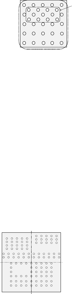
When a component has a staggered pattern of elements partially as shown in
Figure 5.2.4.4.12, divide them into two grid arrangement groups, then define them.
Figure 5.2.4.4.12
① Name
Name an element group to be handled. When you want to change an
element group, specify its name to edit it.
A name is automatically assigned with serial numbers. Users can change this
numbered name to an alphanumeric name (up to 32 characters).
- In the example, the numbered name is used.
② First element position
Specify the position (X, Y) and direction (Theta) of an element group.
As the position, specify the distance (offset) from the center of a component.
Normally, the center of a component is the center of the component outline.
- If the placement coordinates set in Placement data of a production program
is not based on the center of the component outline, you can specify the
coordinates of the reference component center with coordinates different
from the center of the component outline.
Figure 5.2.4.4.13 indicates that the center of the component outline is the
center of a component.
Figure 5.2.4.4.13
Element group 1
Element group 2
Bottom View
Center of a component (Center of
the component outline)
5 − 67
Bottom View
13245
123456
▼ To be precise, the “First element position” is
the distance (offset) from the center of a
component to the first element.
The direction (angle) of the element group is
basically 0 degrees.
Figure 5.2.4.4.14 shows the relation between
the lines (rows) and columns.
The first (ball or land) element positions at the
coordinates of the element (ball/land) at the
lower left corner.
- This layout of elements is different from that of a standard BGA
component having balls on the outer frame.
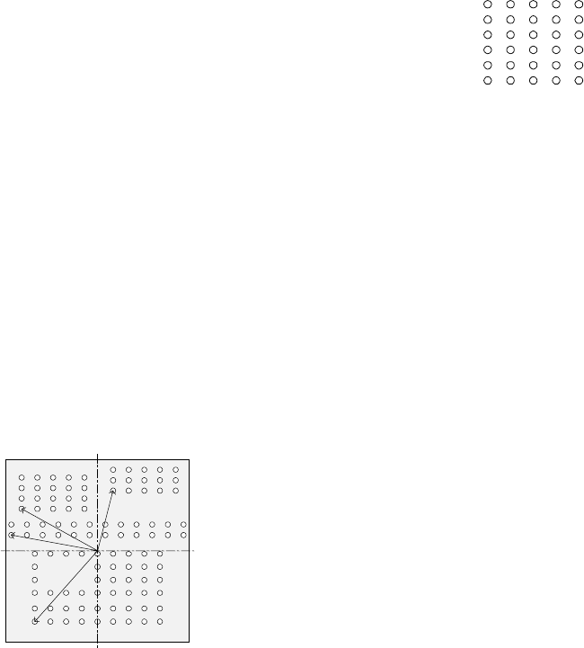
▼ Figure 5.2.4.4.15 shows the first element (ball/land) position of the
component shown in the example above.
For a ball/land element, the center of the first ball/land viewed from the
center of a component becomes the coordinates of the first (ball/land)
element.
Figure 5.2.4.4.15
③ When the first lead end is set to (- 6.0 mm, - 5.0 mm), set each value in the
“First element position” field as follows:
Offset X: - 6.0
Offset Y: - 5.0
Offset Z: 0 (not used)
Offset Theta: 0
- Normally, enter “0” to each field of the setting item “Tolerance”.
• Next, set the element group arrangement.
To set the arrangemen, the setting items “Dimension”, and “Count” and “Pitch”
of the “Column” and “Row” are provided.
Line
(row)
number
Column number
Figure 5.2.4.4.14
Bottom View
Center of a component
(Center of the component outline)
5 − 68
④ Dimension
For a ball/land element, the dimension is two. Select “2D”.
Note: For arrangement of only one column and one row, specify “2D” also.
▼ Figure 5.2.4.4.3 shows the pitch of each element group.
- In the example, the number of lead columns located in the first element
group is nine. Enter “9” to the “Count” field displayed under the setting
item “Column”.
Note: For arrangement of only one line, enter “1”.
- When the pitch is 1.5 mm, enter “1.5” to the “Pitch” of the “Column” field.
Note: For arrangement of only one line, enter “1.5” also.
- Normally, enter “0” to the “Tolerance” field.
- Since the number of lead rows located in the first element group is six,
enter “6” to the “Count” field of the “Row” setting item.
Note: For arrangement of only one row, enter “1” to the “Count” field.
- When the pitch is 1.27 mm, enter “1.27” to the “Pitch” field of the “Row”
setting item.
Note: For an arrangement of one row only, enter “1.27” to the “Pitch”
field too.
- Normally, set “0” to the “Tolerance” field.
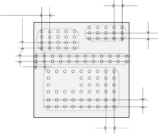
▼ The pitch of each element group is shown in Figure 5.2.4.4.16.
Figure 5.2.4.4.16
⑤ Layout inspection
This item is not used by the current version.
Bottom View
Pitch of the “Column” of the third
element group
Pitch of the “Row” of the third
element group
Pitch of the “Row” of the second
element
g
rou
p
Pitch of the “Column” of the
second element group
Pitch of the “Column” of the
fourth element group
Pitch of the “Row” of the fourth
element group
Pitch of the “Row” of the
first element
g
rou
p
Pitch of the “Column” of
the first element group