KE2040Instruction Manual Ver2.01,REV04.2003.6.25.pdf - 第453页
5 − 63 ⑪ Lead size For a gullwing lead, ent er the lead f oot size here. The “lead f oot size” indicates t he portion of a gullwing lead which is in contact with a board. - I n the example, the leng th of a g ullwing lea…
5 − 62
⑤ Element size
Enter the element size. In the example, the lead length is 1.0 mm, and the
lead width is 0.2 mm. In this case, enter the following values:
Size Width: 0.2
Length: 1.0
Normally, the tolerance is not used. Enter “0” to the “Tolerance” fields.
⑥ Outer Lead/Inner Lead
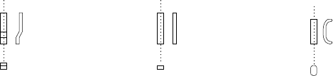
□ Profile (lead shape)
As shown in Figure 5.2.4.4.9, a lead whose shape is flat entirely is called a
“flat lead”, a stepped lead is called a “gullwing lead”, and a J-shaped lead is
called “J-Bend lead”.
* A flat lead is often used for a unidirectional connector.
* A gullwing lead is often used for a QFP and SOP.
* A J-Bend lead is used for a PLCC (QFJ) and SOJ.
Figure 5.2.4.4.9
- In the example, a gullwing lead is shown.
Select “Gullwing” from the “Profile” combo box.
⑦ Cut shape
Specify the shape of a lead end.
All of the settings other than “Flat” are handled in the same manner. When
you select a setting other than “Flat”, set the “Cut width” and “Cut length”
fields.
- In the example, the shape of a lead end is flat.
Select “Flat” from the “Cut shape” combo box.
⑧ Coating
This item is not to be used. Select “Bare” from this combo box.
⑨ Cut width
This item is not to be used. Enter “0” to this field.
⑩ Cut length
Set this item if you select a setting other than “Flat” from the “Cut shape”
combo box.
Enter the length of a not-flat portion measured from the lead end.
- In the example, the shape of a lead end is flat.
Enter “0” to the “Cut length” field.
Gullwing lead
Flat lead
J-Bend lead
5 − 63
⑪ Lead size
For a gullwing lead, enter the lead foot size here.
The “lead foot size” indicates the portion of a gullwing lead which is in contact
with a board.
- In the example, the length of a gullwing lead foot is 0.5 mm.
Enter the following values:
Width: 0.2 (same as the lead width)
Length: 0.4
♦ - Here, you have finished entering element data. When you click the <OK>
button displayed on the lower right corner, the “Element Group” screen
reappears.
- You have finished defining the first element group. When you click the
<OK> button displayed on the lower right corner, the “Extended Vision”
screen reappears.
• When you have the next element group to be defined at this point, click the <Add>
button to define the element group by entering data in the same manner.
In the example, there are four element groups. Define four element groups.
All data to be entered is shown below:
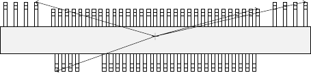
Figure 5.2.4.4.10
Top View
Forth element group
(X, Y): (- 9.50, 5.1) mm
Theta: 180 degrees
Pitch: 0.5 mm, Count: 4
Lead length: 1.2 mm
Lead width: 0.4 mm
Gullwing lead: Flat
Foot length: 0.6 mm
Foot width: 0.4 mm
Third element group
(X, Y): (7.5, 4.9) mm
Theta: 180 degrees
Pitch: 0.5 mm, Count: 31
Lead length: 1.0 mm
Lead width: 0.2 mm
Gullwing lead: Flat
Foot length: 0.4 mm
Foot width: 0.2 mm
Second element group
(X, Y): (13.31, 5.1) mm
Theta: 180 degrees
Pitch: 1.27 mm, Count: 4
Lead length: 1.2 mm
Lead width: 0.4 mm
Gullwing lead: Flat
Foot length: 0.6 mm
First element group
(X, Y): (- 7.25, - 5.1) mm
Theta: 0 degrees
Pitch: 0.5 mm, Count: 30
Missing leads: three from the
fifth lead
Lead length: 1.0 mm
Lead width: 0.2 mm
Gullwing lead: Flat
Foot length: 0.4 mm
Foot width: 0.2 mm
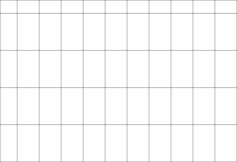
5 − 64
Element
group
name
First
element
position
Layout
inspection
(Dimension)
Missing
elements
Element
Element
offset
Element
size
Element
shape
Cutting Lead size
ELG0001 X:-7.25
Y: -5.1
Z: 0
θ: 0
Tol er an ce :
All set to 0.
√ 25% √ ID
Count of
Column: 30
Pitch of
Column:
0.5
Tolerance:
0
Start: 5
Count: 3
Type: Outer
Lead
Reference
pos.:
Center of the
bottom
Polarity:
Bright
Offset: all
set to 0.
Tolerance:
all set to 0.
Size
X: 0.2
Y: 1.0
Tolerance:
all set to 0.
Profile:
Gullwing
Cut shape:
Flat
Coating:
Bare
Cut width:
0
Cut length:
0
Size
X: 0.2
Y: 0.4
Tolerance:
all set to 0.
ELG0002 X: 13.31
Y: 5.1
Z: 0
θ: 180
Tol er an ce :
All set to 0.
√ 25% √ ID
Count of
Column: 4
Pitch of
Column:
1.27
Tolerance:
0
Type: Outer
Lead
Reference
pos.:
Center of the
bottom
Polarity:
Bright
Offset: all
set to 0.
Tolerance:
all set to 0.
Size
X: 0.4
Y: 1.2
Tolerance:
all set to 0.
Profile:
Gullwing
Cut shape:
Flat
Coating:
Bare
Cut width:
0
Cut length:
0
Size
X: 0.4
Y: 0.6
Tolerance:
all set to 0.
ELG0003 X: 7.5
Y: 4.9
Z: 0
θ: 180
Tol er an ce :
All set to 0.
√ 25% √ ID
Count of
Column: 31
Pitch of
Column:
0.5
Tolerance:
0
Type: Outer
Lead
Reference
pos.:
Center of the
bottom
Polarity:
Bright
Offset: all
set to 0.
Tolerance:
all set to 0.
Size
X: 0.2
Y: 1.0
Tolerance:
all set to 0.
Profile:
Gullwing
Cut shape:
Flat
Coating:
Bare
Cut width:
0
Cut length:
0
Size
X: 0.2
Y: 0.4
Tolerance:
all set to 0.
ELG0004 X: -9.5
Y: 5.1
Z: 0
θ: 180
Tol er an ce :
All set to 0.
√ 25% √ ID
Count of
Column: 4
Pitch of
Column:
1.27
Tolerance:
0
Type: Outer
Lead
Reference
pos.:
Center of the
bottom
Polarity:
Bright
Offset: all
set to 0.
Tolerance:
all set to 0.
Size
X: 0.4
Y: 1.2
Tolerance:
all set to 0.
Profile:
Gullwing
Cut shape:
Flat
Coating:
Bare
Cut width:
0
Cut length:
0
Size
X: 0.4
Y: 0.6
Tolerance:
all set to 0.
Click the <OK> button at the lower left corner of the screen after you define all element groups to finish the “Extended Vision”
data entry.