KE2040Instruction Manual Ver2.01,REV04.2003.6.25.pdf - 第32页
1 − 15 1.1.6 Applicable components and packages (1) Applicable component sizes (For laser recog nition with a KE-2020 only) Table 1-1-6-1 Item Speci fications Component height spec ific ations 12mm 20 mm (option at the f…
1 − 14
1.1.5 Electrical specifications
(1) Number of placement points
Up to 3,000 placement points can be defined per program.
For multi-matrix PWBs, up to 10,000 points can be defined, which is the number
of circuits multiplied by the number of placement points.
(2) Control Systems
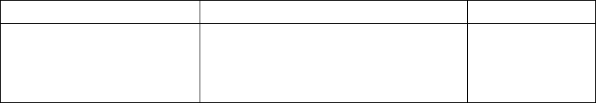
Table 1.1.5.1
Item Control system Resolution
X-Y
Z
θ (MNLA head) *1
θ (FMLA head)
Closed loop by AC servo motor
Semi-closed loop by AC servo motor
Semi-closed loop by AC servo motor
Semi-closed loop by AC servo motor
0.005mm
0.00125mm
0.02°
0.005°
*1 :applicable to a KE-2020
(3) Main CPU
Pentium
(4) Display
Character display : 10.4" color (TTF liquid crystal display panel)
Graphics display : 9" monochrome
(5) Data and program input/output
A program which has been generated with an external programming device or
manually created from the keyboard can be input by means of a 3.5" floppy disk.
(2HD/1.44 MB type only)
When the machine is connected to a host line computer, the LAN interface
permits high-speed communications.
(6) Printer interface
Centronics interface
(7) Power requirements
Voltage : Three-phase, 200 V, 220 V, 240 V
(for Japan)
200 V, 220 V, 240 V, 380 V, 400 V, 415 V
AC
(for the machines to be exported)
Allowable voltage range: ± 10 % (for the rated voltage)
Apparent power : 3 kVA
Frequency : 50/60 Hz
Size of the primary-side power cable : 6 mm
2
or more
Size of the protective grounding lead wire : 6 mm
2
or more
(8) UPS
This machine is equipped with the uninterruptible power supply (UPS) to prevent
data from being damaged or lost due to power failure.
Batteries are used as the back-up power supply of the UPS, so the UPS is
designed to stop the system before these batteries run down. Therefore, even
during power failure, the system can be terminated safely so that any data cannot
be damaged or lost even when a power failure occurs.
1 − 15
1.1.6 Applicable components and packages
(1) Applicable component sizes (For laser recognition with a KE-2020 only)
Table 1-1-6-1
Item Specifications
Component height specifications 12mm
20 mm (option at the factory)
Head Laser recognition
(MNLA)
Laser recognition
(FMLA)
Laser recognition
(MNLA)
Laser recognition
(FMLA)
Min. 0.2 mm
0.3 mm 0.2 mm
0.3 mm Component height
Max. 12 mm 20 mm
Min. 0.6 mm x 0.3 mm
1.0 mm x 0.5 mm
0.6 mm x 0.3 mm
1.0 mm x 0.5 mm
Component size
(Length x Width)
Max. 20 mm x 20 mm
or
26.5 mm x 11 mm
33.5 mm x 33.5 mm
or
Length of a diagonal
line: 47 mm
20 mm x 20 mm
or
26.5 mm x 11 mm
33.5 mm x 33.5 mm
or
Length of a diagonal
line: 47 mm
Lead pitch Min. 0.65 mm
0.65 mm
0.65 mm
0.65 mm
Ball pitch Min. 1.0 mm 1.0 mm 1.0 mm 1.0 mm
Note:
Four nozzles can pick up components whose size is 10 mm x 10 mm or less
simultaneously.
Two nozzles (No. 1 and 3 or No. 2 and 4: one nozzle is skipped) can pick up
components whose size is larger than 10 mm x 10 mm simultaneously.
1 − 16
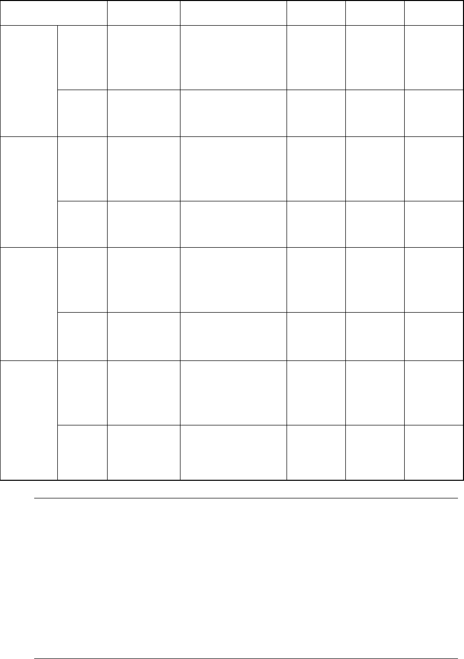
(2) Applicable component (For VCS recognition)
Table 1-1-6-2
Item Partial
recognition
Divided image
recognition
Lead pitch Ball pitch Ball
diameter
Reflective
Minimum:
3 mm x 3 mm
Maximum:
50 mm x 50 mm
Maximum:
50 mm x 150 mm
(when divided into 1 x 3)
Maximum:
74 mm x 74 mm
(when divided into 2 x 2)
Minimum:
0.38 mm
Maximum:
2.54 mm
Minimum:
1.0 mm
Maximum:
3.0 mm
Minimum:
φ 0.4mm
Maximum:
φ 1.0mm
Standard
VCS
(field of view:
54 mm)
Penetrative
Minimum:
9 mm x 9 mm
Maximum:
50 mm x 35 mm
Maximum:
35 mm x 120 mm
(when divided into 1 x 3)
Reflective
Minimum:
3 mm x 3 mm
Maximum:
34 mm x 34 mm
Maximum:
34 mm x 120 mm
(when divided into 1 x 3)
Maximum:
68 mm x 68 mm
(when divided into 2 x 2)
Minimum:
0.3 mm
Maximum:
2.54 mm
Minimum:
0.7 mm
Maximum:
2.0 mm
Minimum:
φ 0.28mm
Maximum:
φ 0.63mm
Optional
VCS-1
(field of view:
37.5 mm)
Penetrative
Minimum:
9 mm x 9 mm
Maximum:
34 mm x 34 mm
Reflective
Minimum:
3 mm x 3 mm
Maximum:
24 mm x 24 mm
Maximum:
24 mm x 72 mm
(when divided into 1 x 3)
Maximum:
48 mm x 48 mm
(when divided into 2 x 2)
Minimum:
0.3 mm
Maximum:
2.54 mm
Minimum:
0.5 mm
Maximum:
2.0 mm
Minimum:
φ 0.2mm
Maximum:
φ 0.63mm
Optional
VCS-2
(field of view:
27 mm)
Penetrative
Minimum:
9 mm x 9 mm
Maximum:
24 mm x 24 mm
Reflective
Minimum:
3 mm x 3 mm
Maximum:
15.5 mm x 15.5
mm
Maximum:
15.5 mm x 46.5 mm
(when divided into 1 x 3)
Maximum:
31 mm x 31 mm
(when divided into 2 x 2)
Minimum:
0.3 mm
Maximum:
2.54 mm
Minimum:
0.35 mm
Maximum:
2.0 mm
Minimum:
φ 0.14mm
Maximum:
φ 0.63mm
Optional
VCS-3
(field of view:
18 mm)
Penetrative
Minimum:
9 mm x 9 mm
Maximum:
15.5 mm x 15.5
mm
Note:
1. The minimum dimensions of a component to be recognized with the VCS are
applied only to a component whose mold dimensions are 7 mm x 7 mm or more.
2. The maximum dimensions of a component to be recognized with the standard
VCS should be within the recognizable range: 52 mm x 52 mm including a
component placement position error and a teaching error which is caused when
the machine picks up the component.
3. The center position of a component should be
±
1 mm or less (in the X and Y
direction) far from the camera center position and the component angle should
be
±
3
°
against the camera center position when the camera is recognizing the
component.