00195655-04_SM_X-Series_FSE_en.pdf - 第101页
Service Work 3.7.1 Replacing the TwinHead Hoses TwinHead Service Manual (internal ver sion) SIPLACE HF and X Series 101 3.7 3 . 7 T w in H e a d TwinHead 3.7.1 3 . 7 . 1 R e p la c in g t h e T w in H e a d H o s e s Rep…
Service Work
C&P6/12 Placement Head 3.6.1 Replacing the Raceway (Circular Arc Guide)
100 Service Manual (internal version) SIPLACE HF and X Series
Installation
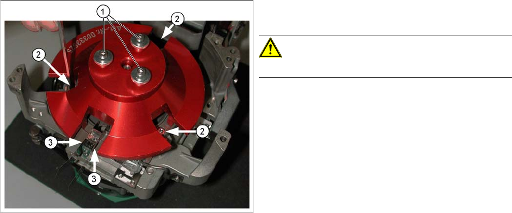
► Fit the 0.01 mm feeler gauges (3) on both side of the Z axis (or the Z axis mechanics gauge).
► Fasten the circular arc guide with the three screws (2).
► Dismantle the gauge for the raceway.
► Remove the feeler gauges and test the Z axis for ease of movement.
► With the help of the feeler gauge, adjust the metal tubes for the air kiss supply to 0.7 mm higher than
the circular arc guide and fix into place with the grub screws (Allen key, 0.71 mm).
► Attach the silicon hose to the metal tubes and fix this to the housing with the hose holders.
► Fit the star back into the head. (see the section "Removing the Star" in the service manual.) Also set
the zero position with the power pack and determine the zero point correction value.
► Insert the tubes into the new raceway but do not yet
tighten the grub screws which fasten these tubes.
CAUTION!
Take care not to bend the tubes.
► Fit the raceway onto the front of the head.
► Fit the raceway gauge onto the motor axis, as shown
in the diagram. Tighten the gauge with the three
screws (1) provided, so that you can reach all the
screws (2) for the raceway and the Z axis.
Service Work
3.7.1 Replacing the TwinHead Hoses TwinHead
Service Manual (internal version) SIPLACE HF and X Series 101
3.7
3.7 TwinHead
TwinHead
3.7.1
3.7.1 Replacing the TwinHead Hoses
Replacing the TwinHead Hoses
Safety instructions
Tools and consumables required
▪ Allen key 1.5 mm
▪ Feeler gauge 0.6 mm
Preparatory steps
► Remove the TwinHead from the machine (see service manual).
Replacing the hoses
WARNING
The safety instructions in the chapter Operational Safety of the operating manual and service
manual take priority.
► The SIPLACE machines are supplied with mains voltage.
Parts of the system therefore carry dangerous voltages! In specific modules the voltage is
present inside the machine base even when the main switch is turned off.
Handling the machines improperly or touching parts thereof which conduct high voltage
may result in death or serious physical injury as well as extensive property damage.
Before performing any work - after correctly shutting down the operating system - switch
the machine off at the main switch and disconnect it from the mains supply.
► In addition, the compressed air supply must be turned off at the main valve of the com
-
pressed air unit, in the machine base, and the compressed air lines must be bled by actu
-
ating the needle valve on the compressed air unit.
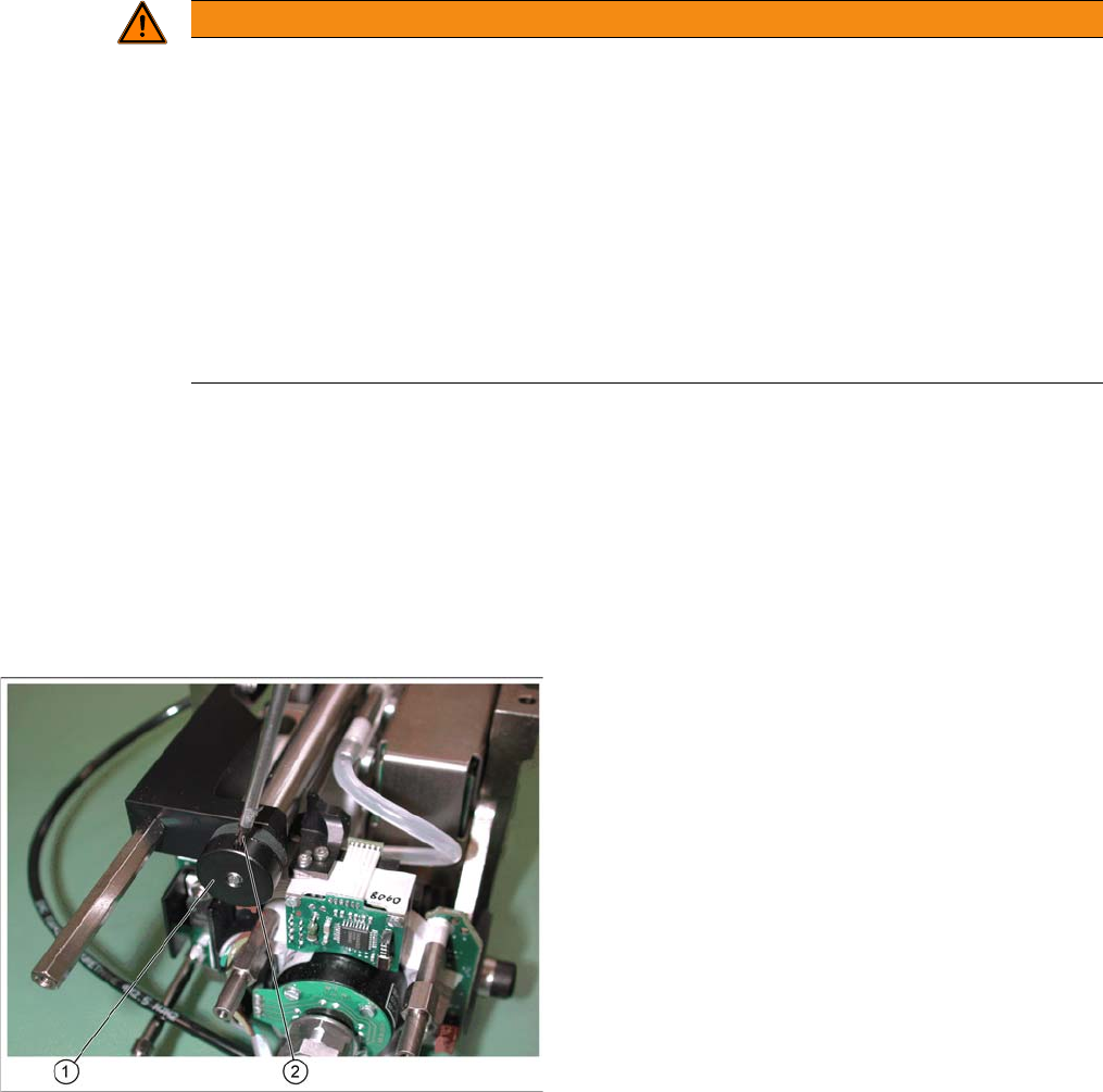
► Loosen the screw (2) fastening the mechanical
bumper (1) .
► Move the stopper back and forth several times and
then unscrew it.
Service Work
TwinHead 3.7.1 Replacing the TwinHead Hoses
102 Service Manual (internal version) SIPLACE HF and X Series
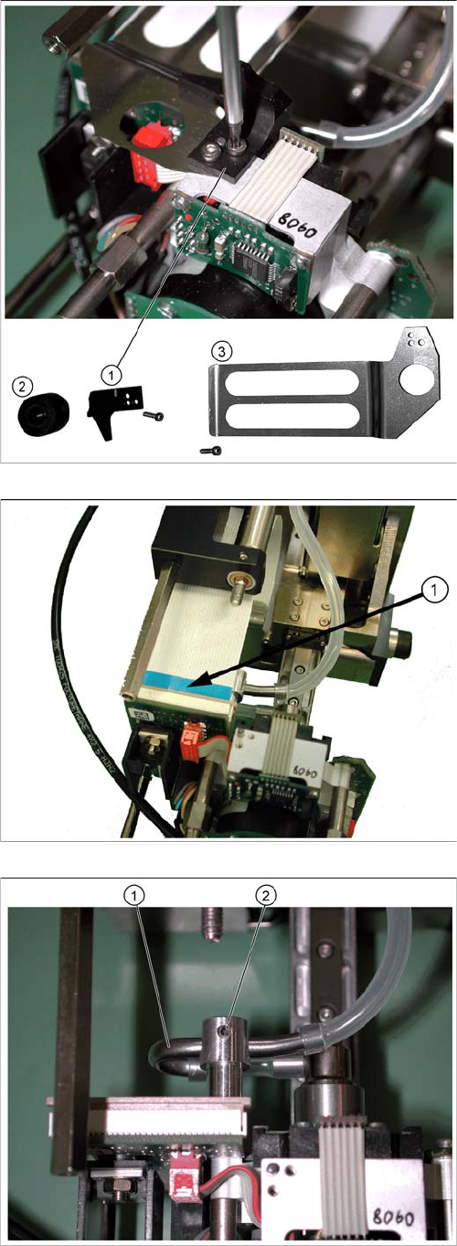
1. Stopper for return unit
2. Mechanical bumper
3. Flat ribbon baffle
► Loosen the two screws (M2x6) on the return unit
stopper.
Remove the flat ribbon baffle.
► Carefully disconnect the flat ribbon cable plug (1) .
► Loosen the screw (2), fastening the elbow (1) .