00195655-04_SM_X-Series_FSE_en.pdf - 第72页
Service Work Gantries 3.3.11 Fitting and Removing the Y Axis Bumper 72 Ser vice Manual (internal ver sion) SIPLACE HF and X Series ► Tighten the four screws fastenin g the stopper with a torque of 3N m . 1. Y stopper 2. …
Service Work
3.3.11 Fitting and Removing the Y Axis Bumper Gantries
Service Manual (internal version) SIPLACE HF and X Series 71
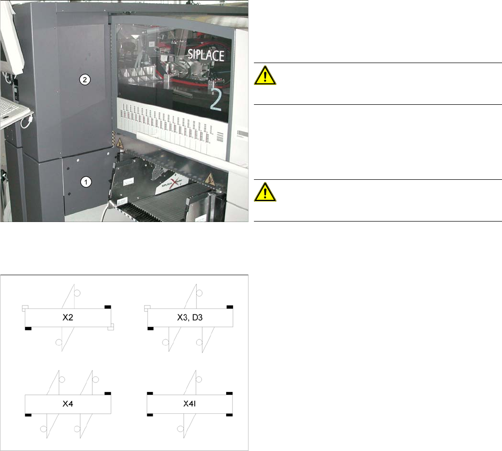
Removal for X4I
Installation
► Remove the relevant changeover table from the ma
-
chine.
► Undo and remove the two screws fastening the bot
-
tom cover (1).
CAUTION!
Take care not to lose the screws etc..
► Undo and remove the two screws fastening the upper
cover (2).
► Loosen the coated fastening screws on the Y stopper
and remove them.
CAUTION!
Take care not to lose the washers and friction foils.
All the Y stoppers marked black in the diagram need to
be fitted with the help of the angle disc.
Service Work
Gantries 3.3.11 Fitting and Removing the Y Axis Bumper
72 Service Manual (internal version) SIPLACE HF and X Series
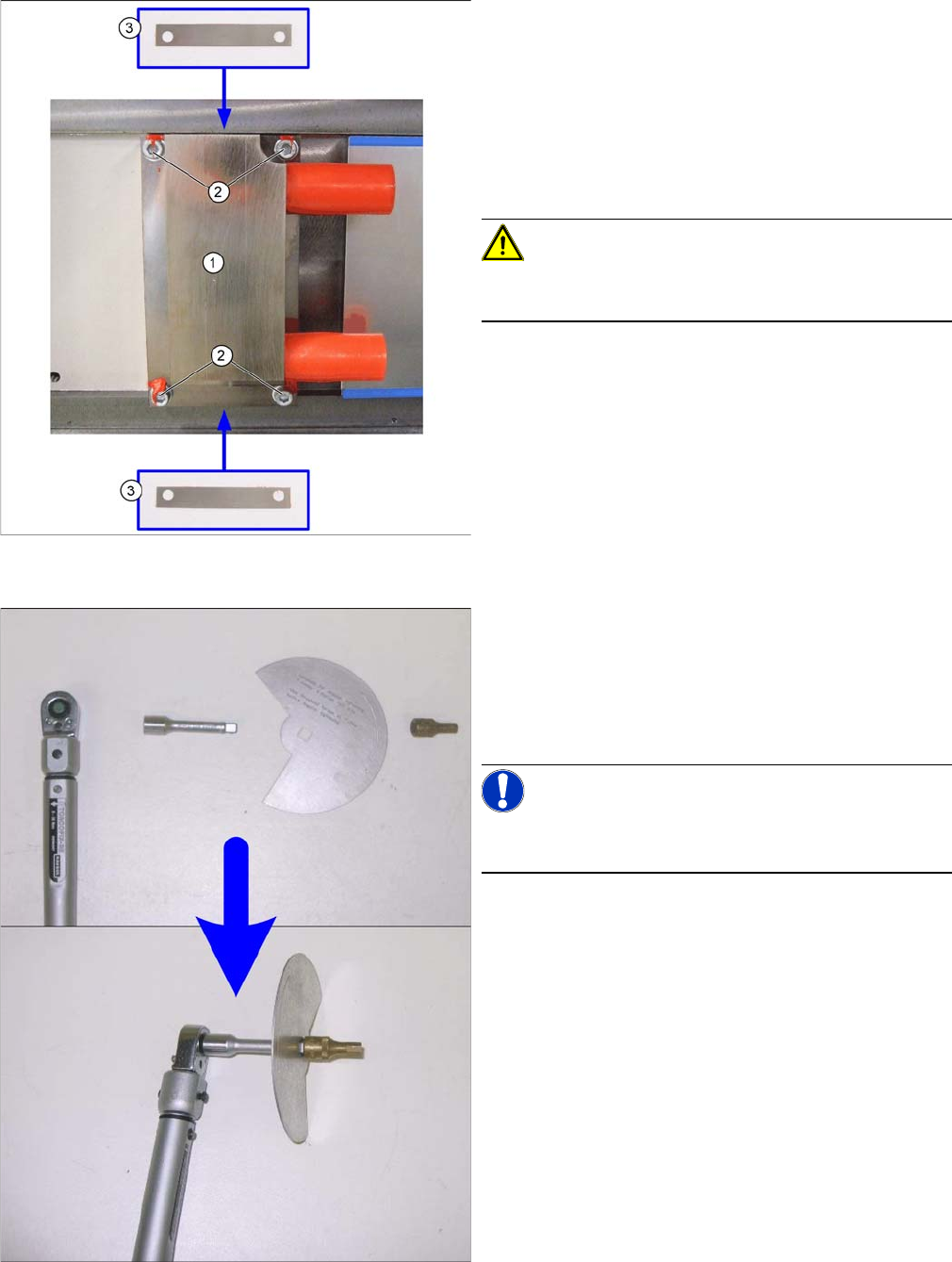
► Tighten the four screws fastening the stopper with a torque of 3Nm.
1. Y stopper
2. Fastening screws with washers
3. Friction foils
► Place the friction foils (3) between the stopper and
machine base, at the angle shown in the diagram.
Observe the asymmetrical drillings on the friction
foils. Screw the stopper loosely on the machine base
with the washers and the new screws (2).
CAUTION!
Make sure that you always use new screws. Do not use
the old screws as these could break!
► Fit the torque key together with the extension, rotary
angle disc and a screwdriver bit for hexagonal sock
-
et-head screws (size 5), as shown in the following di
-
agrams. Set a torque of over 20 Nm, as the expected
torque after tightening the angle disc will be approx.
18 Nm.
NOTICE!
You can also use a conventional ratchet as only the angle
is important for correctly tightening the screws.
Service Work
3.3.11 Fitting and Removing the Y Axis Bumper Gantries
Service Manual (internal version) SIPLACE HF and X Series 73
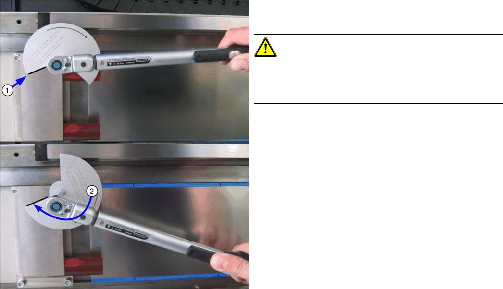
► Fit the torque key onto the screw to be tightened and
mark the bumper block appropriately (1).
CAUTION!
Highlight
When marking and tightening, try to look at the disc from
a straight angle, to avoid parallax errors.
► Turn the screw in a clockwise direction until the sec
-
ond edge of the recess is level with the mark. This is
an angle of 112 degrees.
► After performing this task, apply locking varnish to all
four Y stopper fastening screws.