00195655-04_SM_X-Series_FSE_en.pdf - 第58页
Service Work Gantries 3.3.6 Replacing the X Axis Incremental Encode r 58 Ser vice Manual (internal ver sion) SIPLACE HF and X Series 3.3.6 3 . 3 . 6 R e p la c in g t h e X A x is I n c r e m e n t a l E n c o d e r Repl…
Service Work
3.3.5 Replacing the X Drive (Primary) [03039726-xx] Gantries
Service Manual (internal version) SIPLACE HF and X Series 57
3.3.5.1
3.3.5.1 Installation Check for Guide Trolley and Motor Support
Installation Check for Guide Trolley and Motor Support
Installation check
1. Motor plate
2. Guide trolley
3. Distance 0.5 mm
► During installation, place a 0.5 mm feeler gauge be
-
tween the motor plate and the linear guide
. For adjustment purposes, you may need to remove
the X drive and reposition it.
► Check the gap between the X drive and the magnet
cover with a 0.4 mm thickness gauge.
► To do this, place the thickness gauge between the X
drive and the magnet cover and then push the X drive
back and forth along the entire length. Make sure
none of the parts jam.
Service Work
Gantries 3.3.6 Replacing the X Axis Incremental Encoder
58 Service Manual (internal version) SIPLACE HF and X Series
3.3.6
3.3.6 Replacing the X Axis Incremental Encoder
Replacing the X Axis Incremental Encoder
Please also observe the technical information "Overview of Scales and Read Heads" [DE: TI2014-
05D11] [EN: TI2014-05E11].
Parts, Equipment and Tools
▪ Read head MS22.74 X/Y 677mm [03090201-xx] (replaces: [03020588-xx])
Overview
Press-fit connections
NOTICE
Head interface
The new read head for the X axis "Read head MS22.74 X/Y 677 mm [03090201-xx] may only
be fitted with a "head interface" from FS06 [03000901-06] or a "mirrored head interface" from
FS03 [03029048-03].
The read head can only be fitted together with the new "Tape measure X axis SX4" [03092558-
xx]. If an old read head is upgraded to the new version MS22, you will also need to replace the
scale.
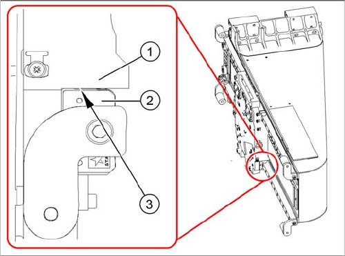
1. Installation point for head interface and Vision board
2. Incremental encoder position
► Unplug the incremental encoder press-fit connection
(2) from the head interface (1).
1
2
Assembly Gantry Board Connectors
X axis incremental en
-
coder
Gantry 1 (C&P head ) Head interface
[03000901
-
xx]
X15ac
X axis incremental en
-
coder
Gantry 2 (TwinHead) Head interface
[03000901
-
xx]
X15bc
Service Work
3.3.6 Replacing the X Axis Incremental Encoder Gantries
Service Manual (internal version) SIPLACE HF and X Series 59
Removal
Installation
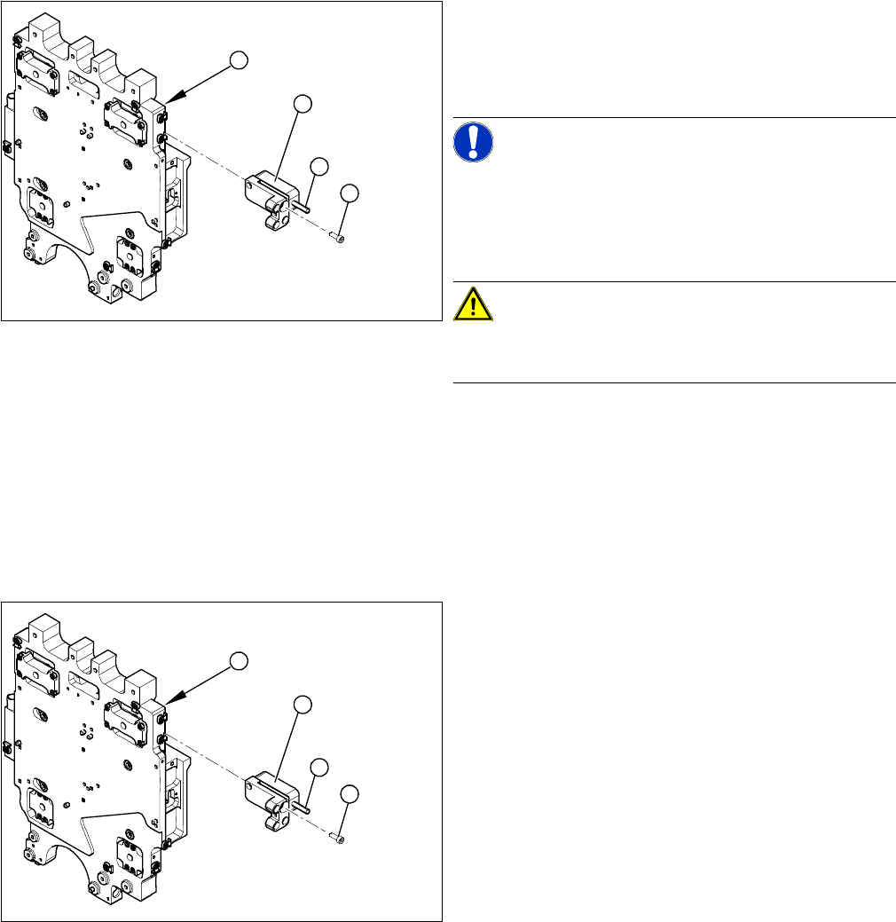
1. Head plate - front view
2. Incremental encoder
3. Three fastening screws
4. Grub screw (secured with Loctite No. 241)
NOTICE!
Grub screw on the incremental encoder
If the incremental encoder is installed on the head plate
of a CFK 04 or 06 gantry, the grub screw is without func
-
tion. Do not loosen or tighten this grub screw.
CAUTION!
HF – CFK02 gantry
Refer to the relevant guide for the CFK02 gantry.
► Unthread the connection cable as far as the incre
-
mental encoder (2).
► Loosen the three screws (3) fastening the incremen
-
tal encoder (2) of the X axis and carefully lift off the
incremental encoder.
3
4
1
2
► Clean the reading surface of the incremental encoder
with a cloth and ethanol or with a cleansing tip.
► Loosely fasten the incremental encoder (2) with three
fastening screws (3).
► The incremental encoder must be aligned with a
0.75 mm gap (for the old read head [03020588-xx]
0.4 mm) to the scale. Use the corresponding thick
-
ness gauge (plastic).
3
4
1
2