00195655-04_SM_X-Series_FSE_en.pdf - 第88页
Service Work C&P20 Placement Head 3.5.2 Settings the C&P20 (FSE) Jaws 88 Ser vice Manual (internal ver sion) SIPLACE HF and X Series 3.5.2.2 3 . 5 . 2 . 2 B a s ic s Basics The jaws need to be correctly set, to e…
Service Work
3.5.2 Settings the C&P20 (FSE) Jaws C&P20 Placement Head
Service Manual (internal version) SIPLACE HF and X Series 87
3.5.2
3.5.2 Settings the C&P20 (FSE) Jaws
Settings the C&P20 (FSE) Jaws
3.5.2.1
3.5.2.1 General
General
Contents of service kit for setting C&P20 jaws [03058847-01]:
▪ Jaw setting gauge with 2x hexagon socket-head screw M2.5x12 mm [03045455-01]
▪ 4 x feeler gauge 0.01 mm [03058840-01]
▪ Feeler gauge 0.04 mm [03058839-01]
▪ Hose piece D12 length 20 mm [03058392-01]
▪ Rubber hose to protect the component sensor
▪ 10x dead indexing plate [03013091-01]
Tools required:
▪ Phillips screwdriver with torque limiter, set to 35 Ncm
▪ Head mounting rack
▪ Hexagon socket-head wrench
NOTICE
SIPLACE Service
This setting may only be performed by the SIPLACE service team!
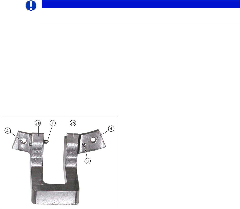
Jaw setting gauge
1. Side stop for jaws
2. 2a and 2b: contact surfaces for jaws
3. Centering pins for accurate setting to raceway
4. Gauge fixture on raceway (screws --> M2.5x12 mm)
Service Work
C&P20 Placement Head 3.5.2 Settings the C&P20 (FSE) Jaws
88 Service Manual (internal version) SIPLACE HF and X Series
3.5.2.2
3.5.2.2 Basics
Basics
The jaws need to be correctly set, to ensure that the bridge between the raceway and jaws is accurate.
The correct height between the raceway and jaws is achieved by determining the zero point correction
value for the Z axis.
When fitting the jaws at the Z axis, you can rotate the jaws. Use the setting gauge to set the correct angle
of the jaws to the raceway.
When do you need to set the jaws?
▪ When replacing the light barrier down, check the position of the jaws (in SITEST).
▪ When fitting the new Z axis drive.
▪ When error messages are issued by the station software (e.g. reference run).
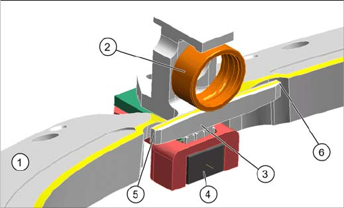
Raceway with Z axis
1. Raceway
2. Ball bearing on segment
3. Snap jaws
4. Light barrier down
5. Bridge raceway – jaws, left
6. Bridge raceway – jaws, right
Service Work
3.5.2 Settings the C&P20 (FSE) Jaws C&P20 Placement Head
Service Manual (internal version) SIPLACE HF and X Series 89
3.5.2.3
3.5.2.3 Procedure
Procedure
Preparatory steps
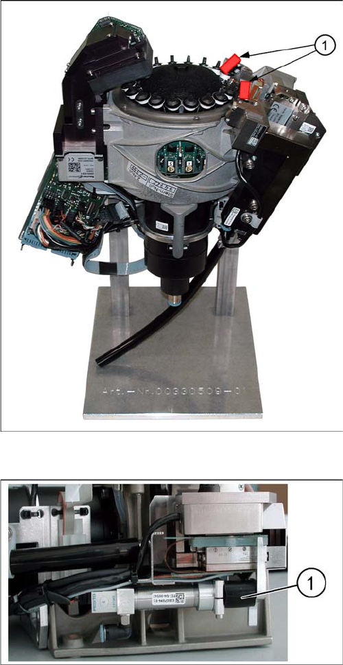
C&P20 placement head on placement head base
1. Red rubber hose - length approx. 20 mm
► To protect the component sensor, fit the red rubber
hose (1) onto the component sensor prisms. (Cut the
rubber hose into two 20 mm pieces.)
► Remove the placement head from the placement ma
-
chine.
► Fit the placement head onto the head rack
[00330509-01] (see diagram).
Fitting the hose piece onto the return unit
1. Hose for return unit
► Clamp the black hose piece D12 20 mm (1) from the
service pack, between the actuator and the housing
of the return unit.
This ensures that the Z axis can still be moved for lat
-
er adjustment and the return unit does not need to be
dismantled.