00195655-04_SM_X-Series_FSE_en.pdf - 第109页
Service Work 3.9.1 Replacing the Cutter Blades [03009259-xx] Cutter Service Manual (internal ver sion) SIPLACE HF and X Series 109 Preparation Installation ► Use an SW 10 open-en ded wrench to push against th e r elevant…
Service Work
Cutter 3.9.1 Replacing the Cutter Blades [03009259-xx]
108 Service Manual (internal version) SIPLACE HF and X Series
Installation – requirements
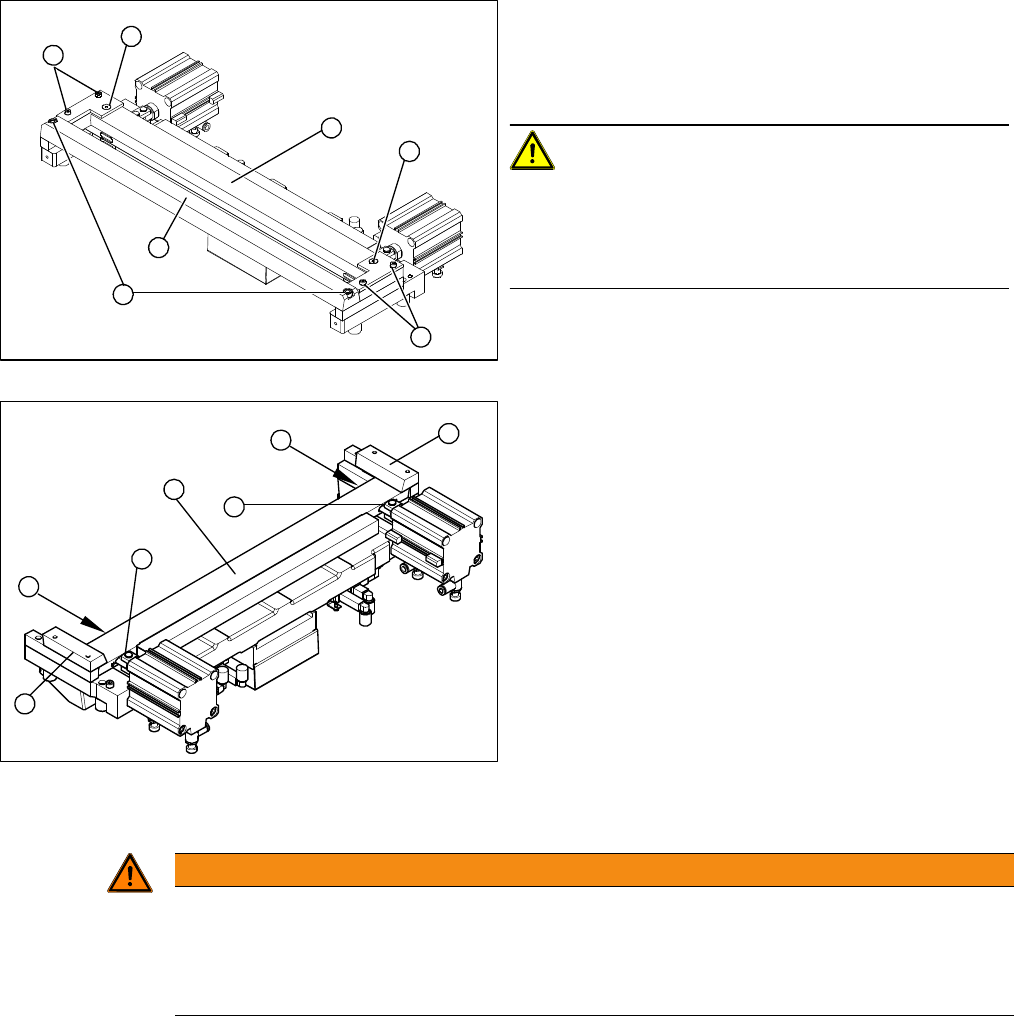
► Loosen and remove the two screws (1) fastening the
stationary blade (2).
► Loosen the screws fastening the left and right tape
deflectors (3) above the moveable blade.
CAUTION!
Do not loosen the two Phillips screws (4).
Remove the tape deflector holder with the tape deflector
(5) and carefully place the whole unit down (with the tape
deflector facing upwards).
► Remove the right-hand holding-down device (1) and
the left holding-down device (2), plus the spacers be
-
low.
► Use an SW 10 open-ended wrench to push against
the joint (3), while loosening the hexagon socket-
head screw of the joint (4) in the moveable blade.
This may require more strength than usual as the
screws have been secured with Loctite no. 243.
► Grasp both ends of the moveable blade (5) with the
protective gloves and pull it upwards and out.
4
3
5
1
4
3
2
3
4
1
5
4
3
2
WARNING
Risk of injury
There is a high risk of injury from the blades and the tape deflector.
► Wear appropriately thick protective gloves!
► Make sure all parts are clean before installing them.
Service Work
3.9.1 Replacing the Cutter Blades [03009259-xx] Cutter
Service Manual (internal version) SIPLACE HF and X Series 109
Preparation
Installation
► Use an SW 10 open-ended wrench to push against the relevant joint (3) and then tighten both screws
(2) to a torque of 2.7 – 3.0 N.
► Replace the two covers (caps).
► Place the 2 new spacers (4) to the left and right of the moveable blade. The spacer side marked with
a number must face away from the blade.
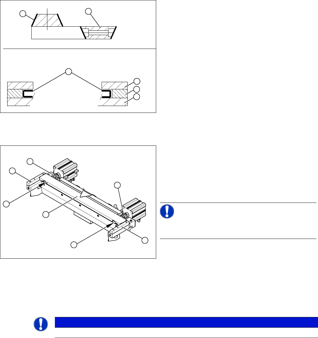
1. Stationary blade
2. Moveable blade
3. Sliding surfaces to be lubricated
4. Holding-down device
5. Spacer
6. Contact surface
► Make sure the cutter is in the correct rotary position
(see the slant of the blade).
► Check the positioning of the individual blades to one
another.
► Before installation, lubricate the sliding surface of the
moveable blade.
1
6
5
4
3
2
► Correctly insert the moveable blade (1) into the cutter
and shift it along to its original installation position.
► Apply Loctite no. 243 to the two M4 screws, to fasten
the joint in the moveable blade.
► Insert the screws (2) into the left and right holes, pro
-
vided in the moveable blade.
NOTICE!
Make sure that the joint (3) can slide into the slot (= anti-
twist function) in the moveable blade without obstruction.
2
3
4
1
4
3
2
NOTICE
The spacers and blades are matched!
Service Work
Cutter 3.9.1 Replacing the Cutter Blades [03009259-xx]
110 Service Manual (internal version) SIPLACE HF and X Series
► Reinsert the tape deflector unit (3) and screw in the 4 hexagon socket-head screws (4) by hand.
► Push the spacers (with inserted shim) as far as possible in the direction of the moveable blade. The
maximum permissible gap is 1.0 mm.
► In this position, tighten the 4 screws (4) on the tape deflector holder crosswise (tightening torque).
► Remove the two feeler gauges.
► Insert the new stationary blade (5) in the correct position and screw tight.
Final work
If the gap is correct:
► Replace the protective plate, baffle plate and cover plate. Make sure that the edges are parallel.
► Remove the clamps form the cutter/ remove the cutter from the assembly plate.
► Fit the cutter.
► Lubricate the contact/slide surfaces for the moveable
blade, as described in the section "Preparation".
CAUTION!
Do not lubricate the blades themselves.
► Place a feeler gauge (0.5 - 1.0 mm thickness) on the
left and right, between the spacer and the front of the
moveable blade (1).
► Place the previously removed holding-down device
(2) onto the new spacers.
⇨ The holding-down devices with function status 03
are designed for use with cutters of function status
-04 (= with tape deflector).
1
2
4
1
5
4
3
2
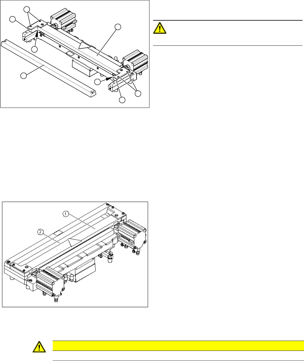
► Use a feeler gauge to check the gap between the
tape deflector (1) and the moveable blade (2), along
the entire length and width of the blade.
⇨ The 0.05 mm feeler gauge should fit through the
gap.
⇨ The 0.25 mm feeler gauge should not fit through
the gap.
If the gap is not correct, check:
▪ Whether the wrong holding-down device has been in
-
stalled (with function status < 03)
▪ The holding-down devices are those designed for
cutters with function status -04 (= with tape deflector)!
▪ Whether the blades, tape deflector etc. were cleaned
before installation
CAUTION
Make sure that the cables and hoses are not trapped or subjected to excess strain.