00195655-04_SM_X-Series_FSE_en.pdf - 第80页
Service Work Modular PCB Conveyor System 3.4.5 Replacing the Proximity Switch for the Adjustment System [00369018-xx] 80 Ser vice Manual (internal ver sion) SIPLACE HF and X Series 3.4.5 3 . 4 . 5 R e p la c in g t h e P…
Service Work
3.4.4 Replacing the Cylinder Switch for the Adjustment Unit [00369016-xx] Modular PCB Conveyor System
Service Manual (internal version) SIPLACE HF and X Series 79
3.4.4
3.4.4 Replacing the Cylinder Switch for the Adjustment Unit [00369016-xx]
Replacing the Cylinder Switch for the Adjustment Unit [00369016-xx]
Parts
▪ Cylinder switch – adjustment unit 1 [00369016-xx]
▪ Cylinder switch - adjustment unit 2 [00369017-xx]
▪ Cylinder switch - adjustment unit 3 [00365572-xx]
Overview
The cylinder switch on the adjustment unit cylinder should operate when the adjustment unit pin is
pushed out by the pneumatic cylinder and therefore connected to the conveyor side. This signal enables
the width adjustment motor.
Removal/Installation
► Adjust the width until the cylinder switch switches - LED (H36/H37) shines.
Connect the cylinder - i.e. the cylinders are moved upwards, as far as the end stop, using the control
unit.
► Set the cylinder switch so that the LED lights up when it is in engaged mode.
► Fix the position of the cylinder switch (2) with the grub screw.
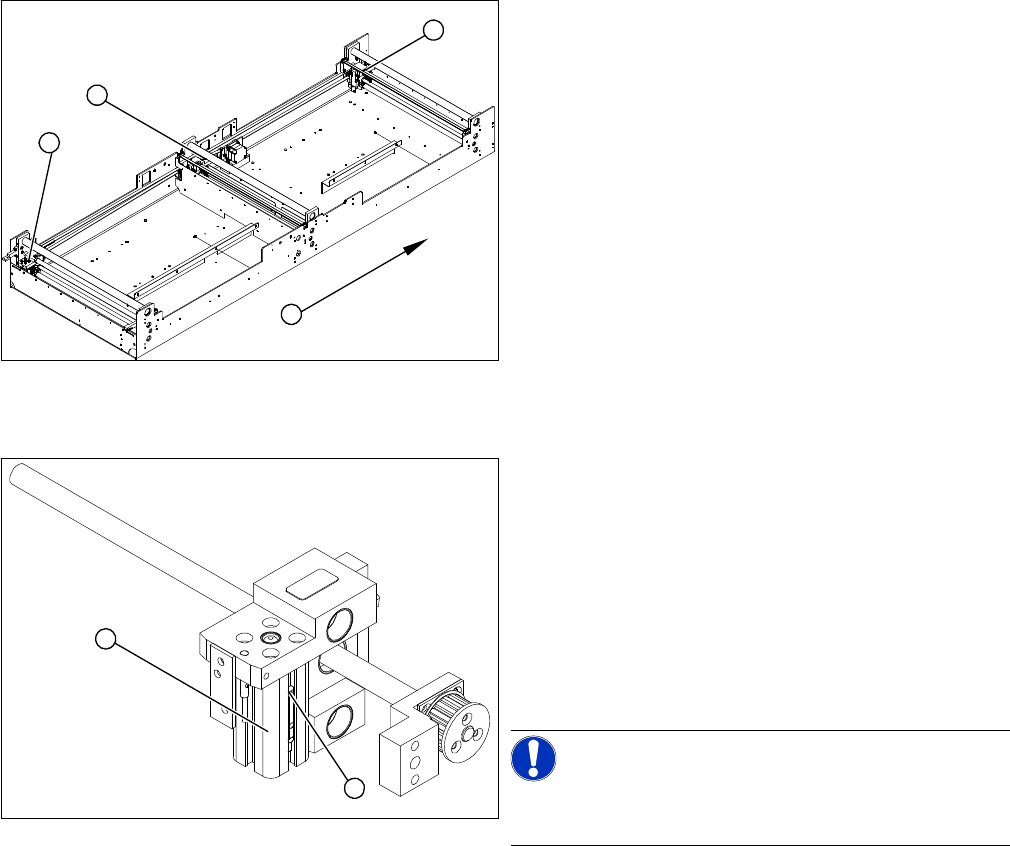
1. Adjustment unit 1
2. Adjustment unit 3
3. Adjustment unit 2
4. Transport direction
► Move the PCB conveyor to the position which gives
you best access to the adjustment system.
► Move the Y gantries into the area outside the PCB
conveyor.
► Switch off the machine and secure it to prevent unau
-
thorized reactivation.
► Switch off the compressed air supply.
3
4
1
2
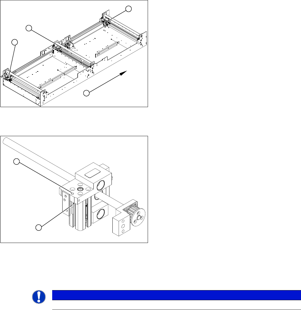
► Loosen the grub screw at the cylinder switch (1) and
push the cylinder switch out of the adjustment unit
guide rail (2).
► Unthread the connection cable as far as the conver
-
sion board of the assembly tub.
► Run the connection cable of the new cylinder switch
(2).
► Insert the new cylinder switch into the guide rail.
► Switch the machine on.
NOTICE!
The width adjustment system cylinder switch is set in en
-
gaged mode.
2
1
Service Work
Modular PCB Conveyor System 3.4.5 Replacing the Proximity Switch for the Adjustment System [00369018-xx]
80 Service Manual (internal version) SIPLACE HF and X Series
3.4.5
3.4.5 Replacing the Proximity Switch for the Adjustment System [00369018-xx]
Replacing the Proximity Switch for the Adjustment System [00369018-xx]
Parts
▪ Proximity switch for adjustment unit 1 [00369018-xx]
▪ Proximity switch for adjustment unit 2 [00369019-xx]
▪ Proximity switch for adjustment unit 3 [00365573-xx]
Overview
The proximity switch serves as a signal for controlling the pneumatic valve of the adjustment unit. Once
the switching point has been reached, the conveyor edge is connected via the short-stroke cylinder.
Removal/Installation
The switching point is set at the actuator on the conveyor edge:
► Move the adjustment unit until it is under the conveyor edge.
► Place a 2/10 mm distance gauge on the adjustment unit, press the actuator onto the distance gauge
and tighten the screw.
► Use the SITEST program to calibrate the conveyor edges.
1. Adjustment unit 1
2. Adjustment unit 3
3. Adjustment unit 2
4. Transport direction
► Move the PCB conveyor to the position which gives
you best access to the adjustment system.
► Move the Y gantries into the area outside the PCB
conveyor.
► Switch off the machine and secure it to prevent unau
-
thorized reactivation.
► Switch off the compressed air supply.
3
4
1
2
► Loosen the grub screw on the clamping device (1)
and unthread the connection cable as far as the con
-
version board of the assembly tub.
► Fit the new proximity switch and reconnect the sys
-
tem to the electrical system.
► Fix the proximity switch with the grub screw. The
proximity switch must be level with the adjustment
unit housing (2).
2
1
NOTICE
This setting must be performed at all conveyor edges.
Service Work
3.4.6 Replacing the Actuator for the Width Adjustment System [00355533-xx] Modular PCB Conveyor System
Service Manual (internal version) SIPLACE HF and X Series 81
3.4.6
3.4.6 Replacing the Actuator for the Width Adjustment System [00355533-xx]
Replacing the Actuator for the Width Adjustment System [00355533-xx]
Overview
Removal/Installation
► Move the PCB conveyor to the position which gives you best access to the actuator.
► Move the Y gantries into the area outside the PCB conveyor.
► Switch off the machine and secure it to prevent unauthorized reactivation.
► Switch off the compressed air supply.
► Loosen and remove the screw fastening the actuator.
► Insert the new actuator and screw in loosely.
► The switching point is set at the actuator on the conveyor edge.
Move the adjustment unit under the conveyor edge.
► Place a 2/10 mm distance gauge on the adjustment unit, press the actuator onto the distance gauge
and tighten the screw.
► Calibrate the conveyor edges.
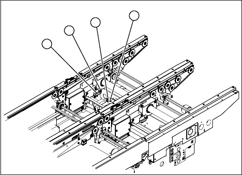
1. Actuator
2. Driver
3. Adjustment unit
4. Proximity switch for adjustment unit
1
4
3
2